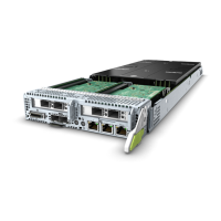
0, 1, 2, and 3. Figure 5-15 shows the internal structure of a memory board
with 12 DIMMs, and Table 5-2 lists the memory channels.
Figure 5-15 Internal structure of a memory board with 12 DIMMs
Table 5-2 Memory channels
Memory
Channel
Composition Primary Slot
Channel 0 J1 J1
J2
J3
Channel 1 J4 J4
J5
J6
Channel 2 J7 J7
J8
J9
Channel 3 J10 J10
J11
J12
Table 5-3 describes DIMM conguration rules.
RH8100 V3 Server
User Guide 5 Removing and Installing Parts of the RH8100 V3
Issue 30 (2019-12-19) Copyright © Huawei Technologies Co., Ltd. 127

 Loading...


