(red)
(black)
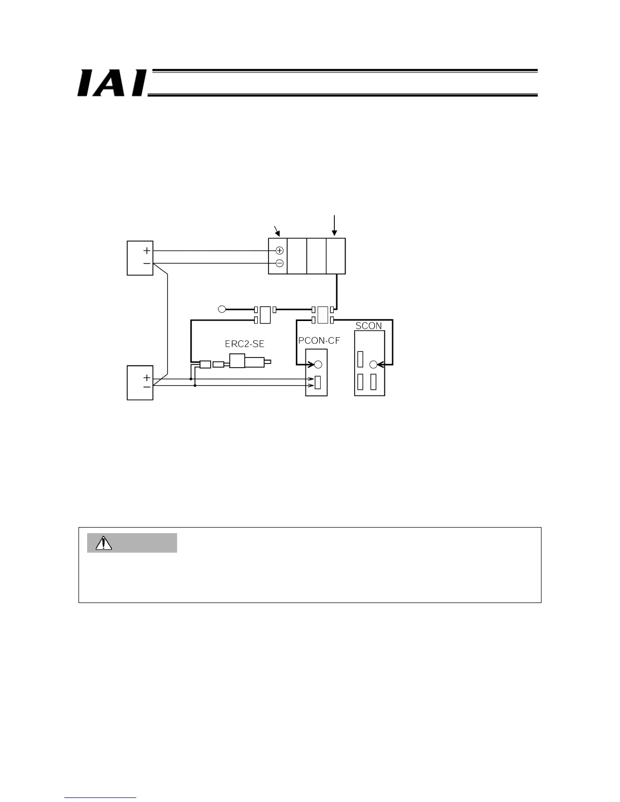
24-V power supply
Extension unit
GatewayR unit
24-V power supply
Terminal resistor
(7) The terminal resistor supplied with the GateWayR unit is not used (not installed to the ROBONET controller).
Install the 220-
Ω terminal resistor supplied with the controller link cable to the 4-way junction at the end of the SIO link.
(8) Use twisted pair cables to connect the power supply (+24 V, 0 V) to the unit positioned at the far left in each ROBONET
stage and also to the controller connected via the external SIO link (ERC2-SE or PCON-CF). The power rise timing
should be the same for each ROBONET stage and the controller connected via the external SIO link.
*1 The SCON power supply is specification single-phase 100 or 200 V.
Example of supplying power from multiple power supplies
Caution
1. Use a common 0-V line for the power supply connected to each ROBONET stage and the controller connected via the
external SIO link.
2. Keep the total distance of internal SIO communication lines of the ROBONET system (distance from the GateWayR unit
to the terminal resistor of the last controller) (including the external SIO link) to 30 m or less.

 Loading...


