yellow
orange
blue
The following parts are supplied.
[1] 4-way junction
[2] e-CON connector
[3] Terminal resistor
Model: 5-1473574-4
4-1473562-4
Outer sheath size of applicable wire
220 Ω 1/4 W
Manufacturer: AMP Quantity: 1
Manufacturer: AMP Quantity: 1
1.35 to 1.6 mm
With e-CON connector Quantity: 1
Controller end
Signal
e-CON connector
3-1473562-4
(Housing color: Orange)
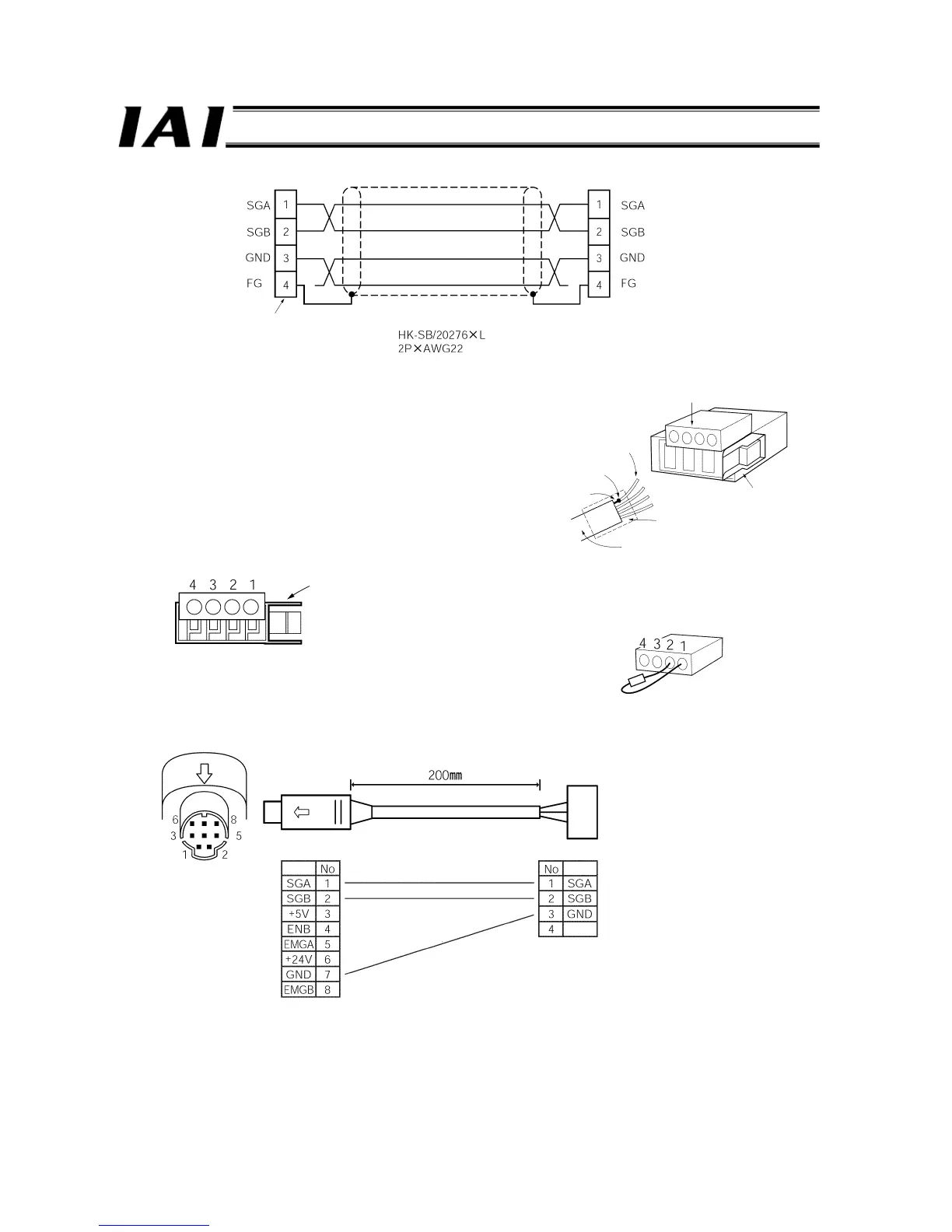
<Fabrication of Junction Interconnection Cable>
[1] Strip the sheath of the 2-pair shielded cable by 15 to 20
mm.
[2] Strand the shielded wires and solder them to vinyl wires
of AWG22 or equivalent.
[3] Slide a cable protection tube onto the cable.
[4] Insert the four core wires into the cable insertion holes in
the connector without stripping the wires. (SDA, SDB,
GND, FG)
[5] With the cable inserted, pressure-weld the press-fit
cable housing from above.
[6] Heat and shrink the cable protection tube.
e-CON connector pin numbers
Be sure to insert a terminal resistor (220
Ω, 1/4 W) at each end of the main
communication line (between Nos. 1 and 2 on the e-CON connector).
<Controller Link Cable> (CB-RCB-CTL002)
This cable is an option for each controller and must be purchased separately.
e-CON connector
Pressure-welded
Vinyl wire
(AWG22)
Soldered
Shielded wire
Locking tab
Cable tube
2-pair shielded cable
Locking tab
e-CON connector
2-pair shielded cable
Recommended: Taiyo Electric Wire & Cable
e-CON connector
(4-1473562-4 by AMP: Green)
Mini-DIN connector
Signal

 Loading...


