368
Appendix
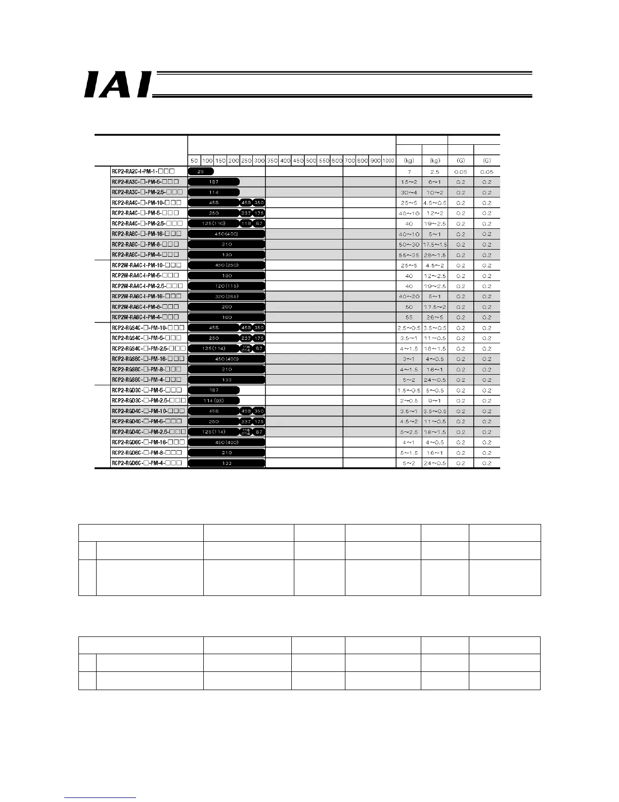
z Rod type
z Gripper
Model Stroke
Maximum
gripping force
Maximum speed Lead
Rated acceleration/
deceleration
RCP2-GRS-I-PM-1-10-P1 10 mm (5 mm per side) 21 N 33.3 mm/s (per side) 1.0 mm 0.3 G
2-
finger
RCP2-GRM-I-PM-1-14-P1 14 mm (7 mm per side) 80 N 36.7 mm/s (per side) 1.1 mm 0.3 G
RCP2-GR3SS-I-PM-30-10-P1 10 mm (5 mm per side) 23 N 40 mm/s (per side) 2.5 mm 0.2 G
RCP2-GR3SM-I-PM-30-14-P1 14 mm (7 mm per side) 120 N 50 mm/s (per side) 3.0 mm 0.2 G
RCP2-GR3LS-I-PM-30-19-P1 19 deg 17 N 200 deg/s (per side) 12 deg 0.2 G
3-finger
RCP2-GR3LM-I-PM-30-19-P1 19 deg 62 N 200 deg/s (per side) 12 deg 0.2 G
z Rotary
Model Oscillation angle
Maximum
torque
Maximum speed
Deceleration
ratio
Rated acceleration/
deceleration
RCP2-RTB-I-PM-20-330-P1 330 deg 1.1 N-m 600 deg/s 1/20 0.3 G
Vertical
RCP2-RTB-I-PM-30-330-P1 330 deg 1.7 N-m 400 deg/s 1/30 0.3 G
RCP2-RTC-I-PM-20-330-P1 330 deg 1.1 N-m 600 deg/s 1/20 0.3 G
Flat
RCP2-RTC-I-PM-30-330-P1 330 deg 1.7 N-m 400 deg/s 1/30 0.3 G
Model
Stroke (mm) and maximum speed (mm/sec) (*1)
Load capacity (*2)
Rated acceleration/
deceleration
Horizontal Vertical
Horizontal Vertical
Standard
(*1) The figure in the elongated circle indicates the maximum speed for each stroke.
The figures in parentheses apply to a vertical application.
(*2) The load capacity is calculated by assuming actuator operation at the rated acceleration.
Splashproof Single-guide Double-guide

 Loading...


