95
INTELLIGENT ACTUATOR
Part 1 Installation
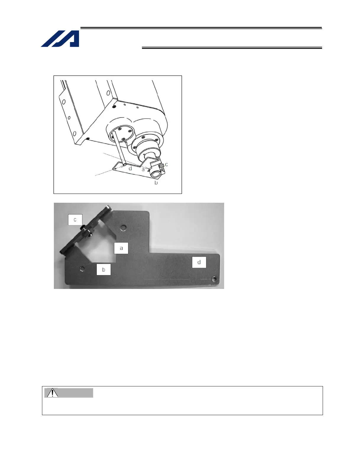
(12) Set the plate and pin constituting the adjustment jig, as shown below, to affix the robot in the
reference posture.
Installation method
[1] Insert the ball-screw spline into the hole in the jig from below.
[2] Cause the D-cut surface of the ball-screw spline to contact the surface a.
[3] Cause the side surface of the ball-screw spline to contact the surface b.
[4] Tighten the screw c to secure the jig onto the ball-screw spline.
* At this time, confirm that the adjustment jig is vertical to the ball-screw spline and that the D-cut
surface and surface a are firmly in contact.
* Applicable screw: Hexagonal socket head setscrew M5
* Tightening torque: 20 [N-cm] (reference)
[5] Insert the supplied shaft into the hole in the ZR unit.
* Exercise caution because the shaft will come off if the hand is released.
[6] Turn the ball-screw spline until the supplied shaft contacts lightly with the surface d of the jig.
Warning
Be sure to keep the emergency stop switch pressed while the adjustment jig is set. If not, the robot
may malfunction and cause serious injury.
D-cut surface
Shaft

 Loading...


