69
INTELLIGENT ACTUATOR
Part 1 Installation
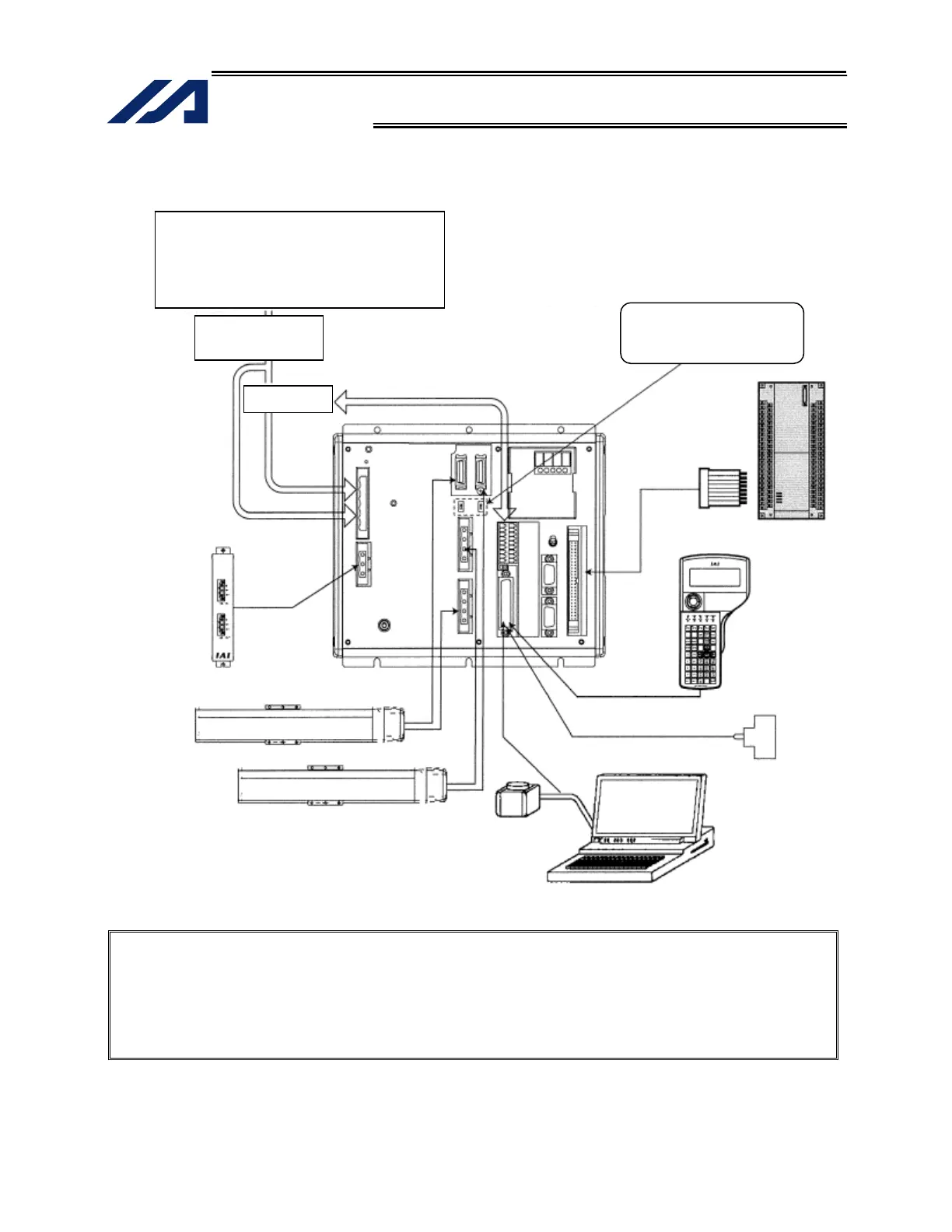
1.2 Connection Diagram for Q Type (Global Specification)
Note 1: With the absolute specification, set the absolute-data backup battery enable/disable switch
to the bottom position for all axes before connecting the encoder/axis-sensor cables. (After
the cables have been connected and power turned on, set the switch back to the top
position.)
Note 2: Connect the supplied dummy plug to the teaching connector if neither a teaching pendant
nor PC cable (PC software) is connected to this connector.
Auxiliary power
device circuit
Absolute-data backup
battery enable/disable
switch
Safety circuit
Axis 1
Regenerative
unit
Host system
(PLC)
Teaching
pendan
(optional)
PC
Axis 2
Dummy plug
(AUTO mode)
Single-phase specification
CP: Single-phase, 200 to 230-VAC power source
MP: Three-phase, 200 to 230-VAC power source
Three-phase specification
CP: Single-phase, 200 to 230-VAC power source
MP: Three-phase, 200 to 230-VAC power source

 Loading...


