1
INTELLIGENT ACTUATOR
Introuduction
Introduction
Thank you for purchasing the X-SEL Controller.
Inappropriate use or handling will prevent this product from demonstrating its full function and may even
cause unexpected failure or result in a shortened service life. Please read this manual carefully, and
handle the product with due care and operate it correctly. Keep this manual in a safe place and reference
relevant items when needed.
The controller types covered by this manual are listed below.
Type Specification
X-SEL-P Standard
X-SEL-Q Global
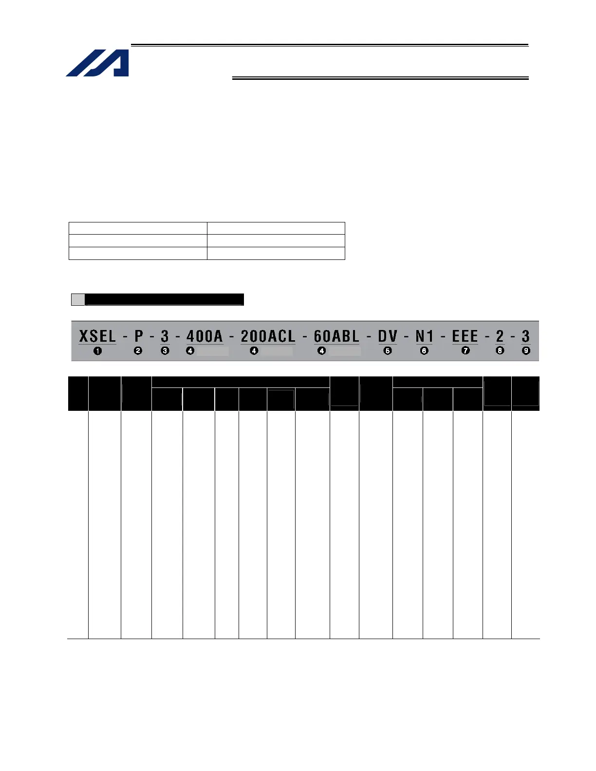
Refer to the following table for details on type specification.
Type
Example of type specification
Type specification table
Details of axis 1 to axis 4 Expanded-I/O slot
Series
Controller
type
Number of
axes
Motor
output (W)
Encoder
type
Brake
Creep
sensor
Home
sensor
(LS)
Synchro
specification
Network
(dedicated
slot)
Standard I/O
(slot 1) Slot 2 Slot 2 Slot 2
I/O flat
cable
length
Power-
source
voltage
XSEL
P
(Standard)
Q
(Safety-
category
compliant)
1
(1 axis)
2
(2 axes)
3
(3 axes)
4
(4 axes)
5
(5 axes)
6
(6 axes)
20
(20W)
30D
(30W for
DS)
30R
(30W for
RS)
60
(60W)
100
(100W)
150
(150W)
200
(200W)
300
(300W)
400
(400W)
600
(600W)
750
(750W)
I
(Incremental)
A
(Absolute)
Blank
(No
brake)
B
(With
brake)
Blank
(No creep
sensor)
C
(With
creep
sensor)
Blank
(No home
sensor)
L
(With
home
sensor)
Blank
(No synchro)
M
(Master axis
specification)
S
(Slave axis
specification)
Blank
(Network
not
available)
DV
(DeviceNet
256/256
board)
CC
(CC-Link
256/256
board)
PR
(ProfiBus
256/256
board)
ET
(Ethernet
Data
communica-
tion board)
E
(Not used)
N1
(Input 32/
Output 16
NPN board)
N2
(Input 16/
Output 32
NPN board)
N3
(Input 48/
Output 48
NPN board)
P1
(Input 32/
Output 18
PNP board)
P2
(Expanded
I/O
PNP16/32)
P3
(Input 48/
Output 48
PNP board)
E
(Not used)
N1
(Expanded
I/O
NPN32/16)
N2
(Expanded
I/O
NPN16/32)
N3
(Multi-point
I/O
NPN48/48)
P1
(Expanded
I/O
PNP32/16)
P2
(Expanded
I/O
PNP16/32)
P3
(Multi-point
I/O
PNP48/48)
S *5
(Expanded
I/O with
base)
E
(Not used)
N1
(Expanded
I/O
NPN32/16)
N2
(Expanded
I/O
NPN16/32)
N3
(Multi-point
I/O
NPN48/48)
P1
(Expanded
I/O
PNP32/16)
P2
(Expanded
I/O
PNP16/32)
P3
(Multi-point
I/O
PNP48/48)
S *5
(Expanded
I/O with
base)
E
(Not used)
N1
(Expanded
I/O
NPN32/16)
N2
(Expanded
I/O
NPN16/32)
N3
(Multi-point
I/O
NPN48/48)
P1
(Expanded
I/O
PNP32/16)
P2
(Expanded
I/O
PNP16/32)
P3
(Multi-point
I/O
PNP48/48)
S *5
(Expanded
I/O with
base)
2: 2 m
(Standard)
3: 3 m
5: 5 m
0: None
2: Single-
phase, 200
V
3: Three-
phase,
200 V
*1 With this type, a safety protection circuit can be configured by separating the motor drive source.
*2 RCS2-R**7 series, RCS-RB75 series, RCS-G20, RCS-R* and linear motor (LCA) actuators cannot be connected as axes 5
and 6.
*3 One large high-thrust linear actuator (W21H) occupies the space of two axes with one axis, so pay attention to the total
number of axes.
*4 [3] indicates the number of connected axes regardless of whether or not the condition in *3 applies.
*5 S indicates that an expanded I/O board will be added later, instead of being installed from the beginning. In this case, the
applicable expanded I/O base slot becomes empty.
(Axis 1)
(Axis 2) (Axis 3)

 Loading...


