22
INTELLIGENT ACTUATOR
Part 1 Installation
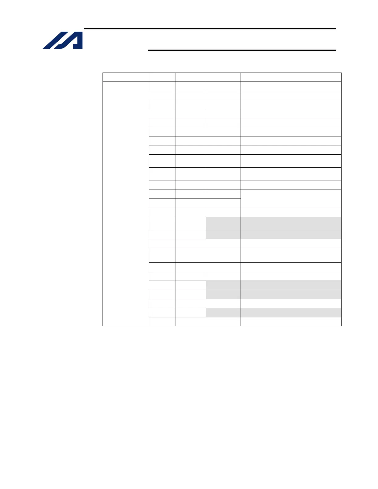
Interface Specifications of Teaching Serial Interface
Item No. Direction Signal name Details
1 FG Frame ground
2 Out TXD Transmitted data
3 In RXD Received data
4 Out RTS Request to send
5 In CTS Clear to send
6 Out DSR Equipment ready
7 SG Signal ground
8 NC Not connected
9 In RSVTBX1
RSV signal line for generic teaching
pendant
10 In RSVTBX2
RSV signal line for generic teaching
pendant
11 NC Not connected
12 Out EMGOUT1 Emergency-stop contact 1
13 In EMGIN1
14 NC Not connected
15 Out RSVVCC
24-V power supply for IA-T-XA/SEL-T
(D) teaching pendant
16 Out EMGOUT2 Emergency-stop contact 2
17 Out ENBVCC1 Enable drive power 1
18 Out VCC
Power output
(power supply for IA-T-
X (D) teaching pendant)
19 In ENBTBX1 Enable input 1
20 In DTR Terminal ready
21 Out ENBVCC2 Enable drive power 2
22 In ENBTBX2 Enable input 2
23 Out EMGS Emergency-stop status
24 In EMGIN2 Emergency-stop contact 2
Terminal
assignments
25 SG Signal ground
Shading indicates that the signal is used only with an ANSI teaching pendant.

 Loading...


