27
INTELLIGENT ACTUATOR
Part 1 Installation
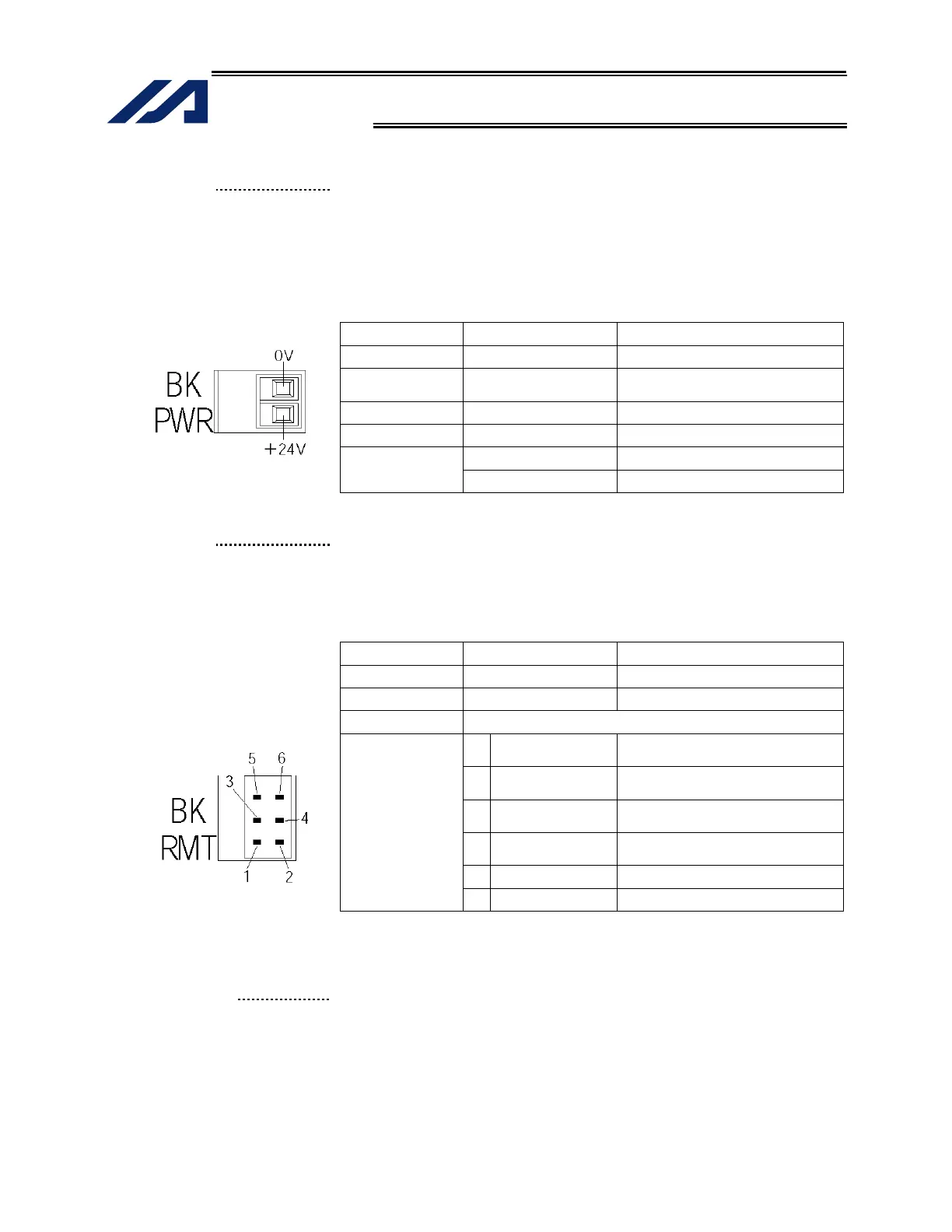
(19) Brake-power input
connector
This connector is used to input the drive power for the actuator brake. 24
VDC must be supplied externally. If the specified brake power is not
supplied, the actuator brake cannot be released. Be sure to supply the
brake power for axes equipped with brake.
As for the brake power cable, use a shielded cable and connect the shield
on the 24-V power side.
The bottom side of the connector connects to +24 V.
Brake Power Connector Specifications
Item Overview Details
Connector Phoenix Contact
MC1.5/2-G-3.5
Cable-end
connector
Phoenix Contact MC1.5/2-ST-3.5
Applicable wire size: AWG28 to 14
Connector name BK PWR
Input voltage
24 VDC 10%
0 V 24-V power ground
Terminal
assignments
+24 V 24-V power input
(20) Brake-release switch
connector
This connector accepts a switch that releases the actuator brake
externally from the controller. Shorting the COM and BKRMT* terminals of
this connector will release the brake. Use this connector if you want to
operate the actuator manually in the event of a power failure or error in the
controller.
Brake-release Switch Connector Specifications
Item Item Overview
Connector Hirose DF11-6DP-2DS (*)
Connector name BK RMT
Connected unit Brake-release switch
1
BKRMT1 (BKRMT5)
Brake-release switch input for axis
1 (5)
2
BKRMT2 (BKRMT6)
Brake-release switch input for axis
2 (6)
3
BKRMT3
Brake-release switch input for axis
3
4
BKRMT4
Brake-release switch input for axis
4
5
COM (COM) Switch input common
Terminal
assignments
6
COM (COM) Switch input common
*) Mating connector --- Hirose socket: DF11-6DS-2C, crimp terminal:
DF11-2428SC
The items in ( ) are for the brake unit for 5/6-axis type.
(21) Brake switch
This alternate switch with lock is used to release the axis brake. To
operate the switch, pull it toward you and tilt.
Tilting the switch upward (RLS side) will release the brake forcibly, while
tilting it downward (NOM) will enable an automatic brake control by the
controller.

 Loading...


