1-13
!5 S/P DIF INPUT TERMINAL [S/P DIF– IN] (p. 2-7)
!6 S/P DIF OUTPUT TERMINAL [S/P DIF– OUT]
(p. 2-7)
ConnectsexternalequipmentthatsupportsS/P
DIF input/output.
!7 ALC LEVEL ADJUSTMENT POT [ALC ADJ]
Adjusts the ALC levels.
No adjustment is required when the ALC output
level of a connected non-Icom linear amplifier is 0
to–4VaDC.
!8 ALC INPUT JACK [ALC] (p. 2-8)
Connects to the ALC output jack of a non-Icom lin-
ear amplifier.
!9 T/R CONTROL JACK [RELAY] (p. 2-8)
Connects to ground when transmitting to control an
externalunit,suchasanon-Icomlinearamplifier.
@0 ACCESSORY SOCKET 1 [ACC 1]
@1 ACCESSORY SOCKET 2 [ACC 2]
Enableconnectionofexternalequipmentsuchas
a linear amplifier, an automatic antenna selector/
tuner, a TNC for data communications, and so on.
•Seepage2-11forsocketinformation.
@2
EXTERNAL SPEAKER JACK [EXT-SP]
(p. 2-6)
Connectsanexternalspeaker(4–8Ω), if desired.
@3 EXTERNAL KEYPAD JACK [EXT KEYPAD]
(p. 2-7)
Connectsanexternalkeypadfordirectvoicemem-
ory or electronic keyer control.
Transceiver mute control line (both transmit and
receive) is also supported.
@4 METER JACK [METER] (p. 2-7)
Outputs a signal showing received signal strength,
transmitoutputpower,VSWR,ALC,speechcom-
pression,V
d or Idlevelforexternalmeterindica-
tion.
@5 DC OUTPUT JACK [DC OUT] (p. 2-7)
Outputsaregulated14VDC(approximately)for
externalequipment.Connectedin parallel with
13.8Voutputsof[ACC1]and[ACC2].(maximum
1 A in total)
@6 TRANSVERTER CONNECTOR [X-VERTER]
(p. 2-6)
Externaltransverterinput/outputconnector.
Activated by voltage applied to [ACC 2] pin 6, or
when the transverter function is in use. (pp. 2-11)
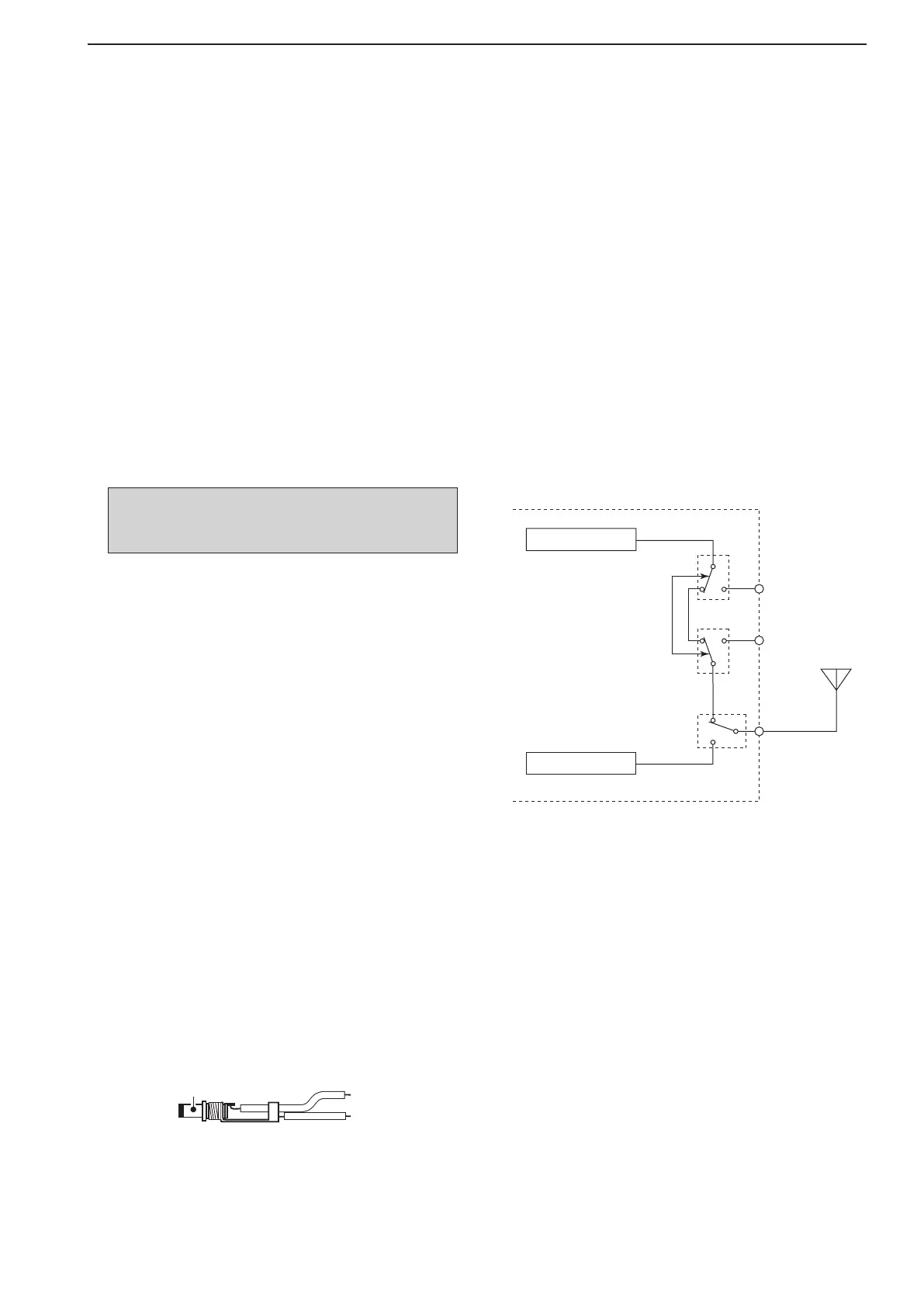
@7 RECEIVE ANTENNA IN [RX ANT– IN]
@8 RECEIVE ANTENNA OUT [RX ANT– OUT]
Located between the transmit/receive switching
circuit and receiver’s RF stage.
Connectsanexternalunit,suchaspreamplifieror
RF filter, using BNC connectors, if desired.
Whennoexternalunitisconnected,[RXANT–
IN] and [RX ANT– OUT] must be deactivated
and shorted by the switching relay internally. This
setting is available on the antenna set screen.
(p. 10-5)
NOTE: T/R control voltage and current must be
lowerthan16VDC/0.5Awith Reed switching or
250VAC/200mAwithMOSFETswitching.
1
PANEL DESCRIPTION
Receiver
Transmitter
IN
[RX ANT]
OUT
Transmit/Receive
switching circuit
ANT