2-2
■ Unpacking
After unpacking, immediately report any damage to the
delivering carrier or dealer. Keep the shipping cartons.
For a description and a diagram of accessory equip-
ment included with the IC-7700, see ‘Supplied acces-
sories’ on page iii of this manual.
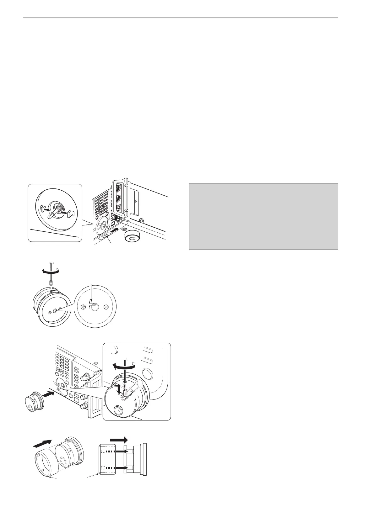
■ Main dial attachment
The main dial is shipped unattached to the transceiver
to prevent possible damage to the dial shaft or rotary
encoder during shipping. Please attach the dial as de-
scribed below.
q Slide the dial brake adjustment to the right position
(Fig. 1).
•Thedialbrakesmoveinwardasshown.
w Insert the main dial set-screw into the screw hole of
the main dial, then tighten the screw until the screw
extendsintotheshaftholeoutslightlyusingsup-
pliedhexagonalwrench(2mm)(Fig.2).
•Becarefulthatthescrewdoesnotextendoutmorethan
1 mm (0.04 in).
e Attach the main dial as illustrated (Fig. 3).
•Becarefultomatchthecorrectorientationoftheflat
face of the shaft and the screw hole of the dial knob.
rTightenthescrewusingsuppliedhexagonalwrench
as illustrated (Fig. 3).
t Install the rubber cover to the main dial (Fig. 4) little
by little.
•Becarefultomatchthecorrectpositionoftheconvex
part of the rubber cover and the concave part of the dial
knob.
•Neverinstalltherubbercoveronthemaindialbyforce.
This may cause damage to the dial shaft or rotary en-
coder.
y Then adjust the main dial brake as desired.
2
INSTALLATION AND CONNECTIONS
Dial brake adjustment
Fig. 1
q
Shorter than
1 mm (0.04 in)
Fig. 2
w
w
CAUTION: NEVER hold any controller knob(s),
such as the main dial, when carrying or lifting the
transceiver. This will damage the dial shaft or rotary
encoder.
Once attaching the rubber cover to the main dial,
it’s hard to remove. When you remove the rubber
cover from main dial, be careful to lack your nails
and/or damage to the transceiver.
Fig. 4
Side view
t
Front side