1-6
■ Front panel (continued)
#5
NOISE REDUCTION SWITCH [NR]
(for MAIN band;
p. 5-19)
#6 NOISE REDUCTION SWITCH [NR] (for SUB band;
p. 5-19)
Push to switch the DSP noise reduction ON or
OFF.
•The[NR]indicatorabovethisswitchlightsgreenwhen
the function is activated.
#7 NOISE REDUCTION LEVEL CONTROL [NR]
(inner control; for SUB band; p. 5-19)
#8 NOISE REDUCTION LEVEL CONTROL [NR]
(inner control; for MAIN band; p. 5-19)
Adjusts the DSP noise reduction level when the
noise reduction is in use. Set for maximum read-
ability.
•Tousethiscontrol,pushtheappropriateband’s[NR].
#9 NOISE BLANKER CONTROL [NB] (outer control;
for MAIN band; p. 5-18)
$0 NOISE BLANKER CONTROL [NB] (outer control;
for SUB band; p. 5-17)
Adjust the noise blanker threshold level.
•To use this control, push appropriate band’s [NB]
switch.
$1 NOISE BLANKER SWITCH [NB] (for MAIN band;
p. 5-18)
$2 NOISE BLANKER SWITCH [NB] (for SUB band;
p. 5-18)
➥ Switches the noise blanker ON or OFF when
pushed. The noise blanker reduces pulse-type
noise such as that generated by automobile ig-
nition systems. This function cannot be used for
FM, or non-pulse-type noise.
•The [NB] indicator above this switch lights green
while the function is activated.
➥ Enters blank-width set mode when held down for
1 second.
$3 RECEIVE INDICATOR [RX] (for MAIN band)
$4 RECEIVE INDICATOR [RX] (for SUB band)
Lights green while receiving a signal and when the
squelch is open.
$5
LOCK INDICATOR [LOCK] (for MAIN band; p. 5-19)
$6
LOCK INDICATOR [LOCK] (for SUB band; p. 5-19)
Lights when the dial lock function is activated.
$7 SPLIT OPERATION INDICATOR [SPLIT]
Lights during split frequency operation.
$8 LCD FUNCTION DISPLAY (p. 1-15)
Shows the operating frequency, function switch
menus, spectrum scope screen, memory channel
screen, set mode settings, etc.
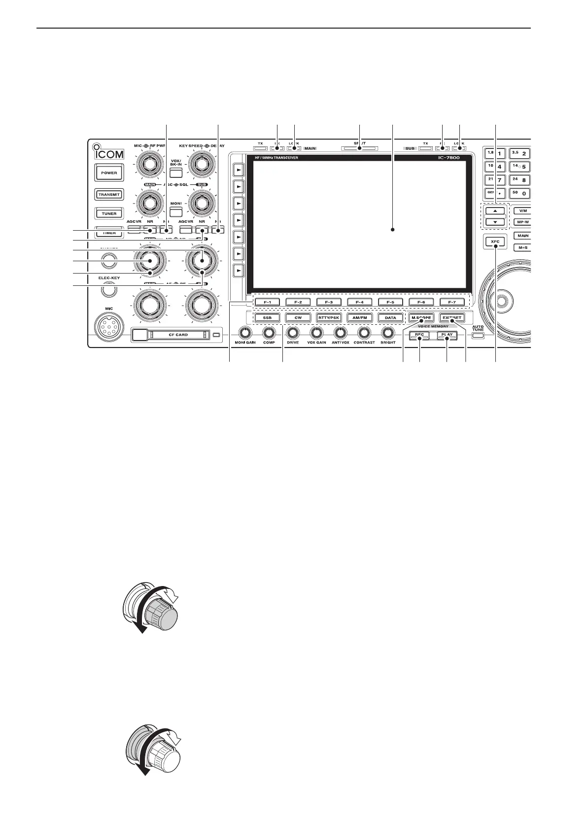
1
PANEL DESCRIPTION
#5
#6
$1 $2
#8
#9
$5$3 $6 $9$4$7 $8
#7
$0