12-8
12
SET MODE
■ ACC set mode (continued)
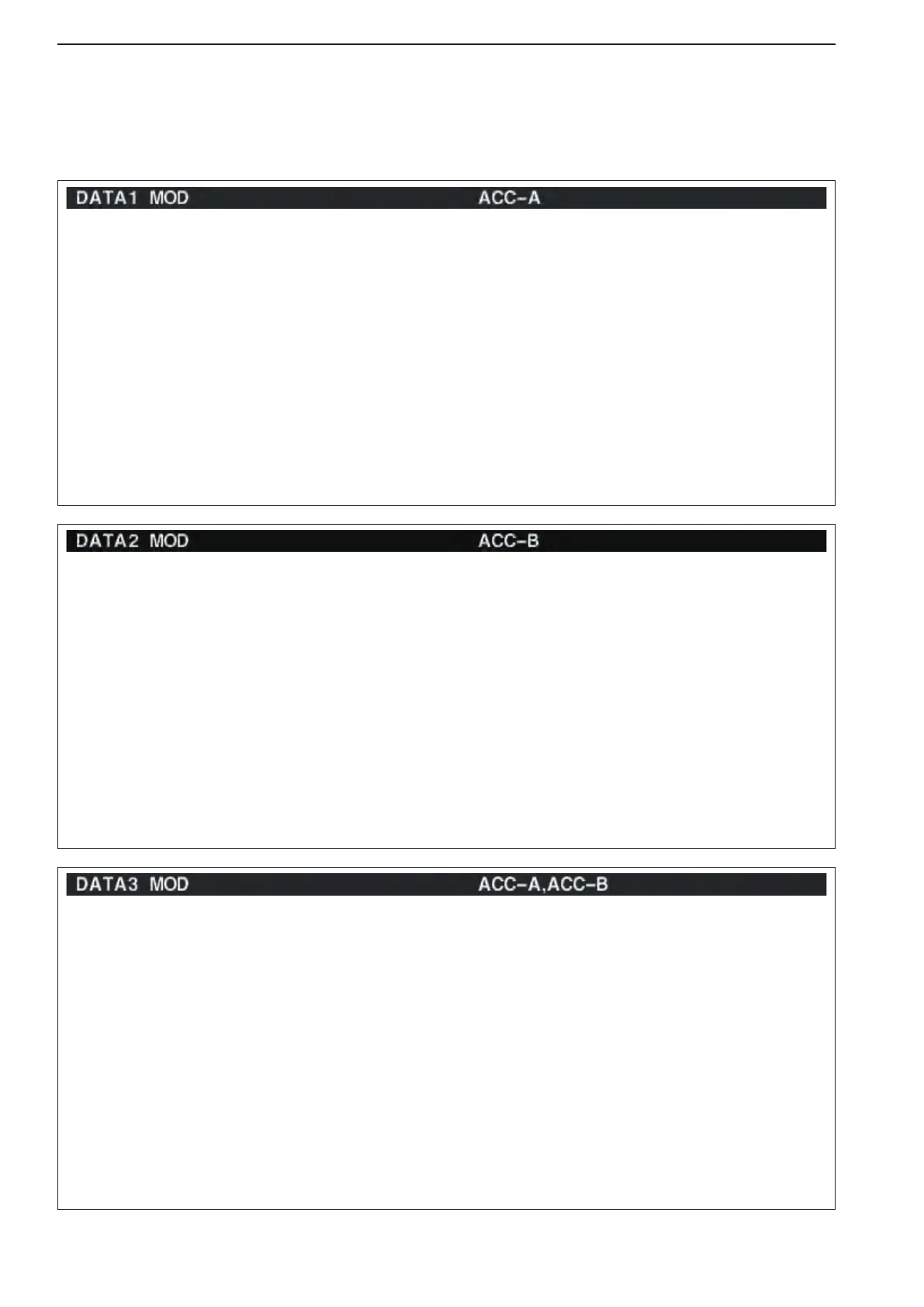
Selects the desired connector(s) for modulation input
when data 2 mode (D2) is in use.
•MIC :Usethesignalsfrom[MIC].
•ACC-A :Usethesignalsfrom[ACC1–A]
(pin 4).
•ACC-B :Usethesignalsfrom[ACC1–B]
(pin 4). (default)
•MIC,ACC-A :Use the signals from [MIC]
and [ACC1–A] (pin 4).
•MIC,ACC-B :Use the signals from [MIC]
and [ACC1–B] (pin 4).
•ACC-A,ACC–B :
Use the signals from [ACC1–A]
and [ACC1–B] (pin 4).
•MIC,ACC-A,ACC–B:
Use the signals from [MIC],
[ACC1–A] and [ACC1–B] (pin 4).
•S/PDIF :
Use the signals from [S/P DIF].
•LAN :Usethesignalsfrom[LAN].
Selects the desired connector(s) for modulation input
when data 3 mode (D3) is in use.
•MIC :Usethesignalsfrom[MIC].
•ACC-A :Usethesignalsfrom[ACC1–A]
(pin 4).
•ACC-B :Usethesignalsfrom[ACC1–B]
(pin 4).
•MIC,ACC-A :Use the signals from [MIC]
and [ACC1–A] (pin 4).
•MIC,ACC-B :Use the signals from [MIC]
and [ACC1–B] (pin 4).
•ACC-A,ACC–B :U se t he s i gna ls f r om
[ACC1–A] and [ACC1–B] (pin
4). (default)
•MIC,ACC-A,ACC–B:
Use the signals from [MIC],
[ACC1–A] and [ACC1–B] (pin 4).
•S/PDIF :
Use the signals from [S/P DIF].
•LAN :Usethesignalsfrom[LAN].
Selects the desired connector(s) for modulation input
when data 1 mode (D1) is in use.
•MIC :Usethesignalsfrom[MIC].
•ACC-A :Usethesignalsfrom[ACC1–A]
(pin 4). (default
•ACC-B :Usethesignalsfrom[ACC1–B]
(pin 4).)
•MIC,ACC-A :Use the signals from [MIC]
and [ACC1–A] (pin 4).
•MIC,ACC-B :Use the signals from [MIC]
and [ACC1–B] (pin 4).
•ACC-A,ACC–B :
Use the signals from [ACC1–A]
and [ACC1–B] (pin 4).
•MIC,ACC-A,ACC–B:
Use the signals from [MIC],
[ACC1–A] and [ACC1–B] (pin 4).
•S/PDIF :
Use the signals from [S/P DIF].
•LAN :Usethesignalsfrom[LAN].