1-10
■ Front panel (continued)
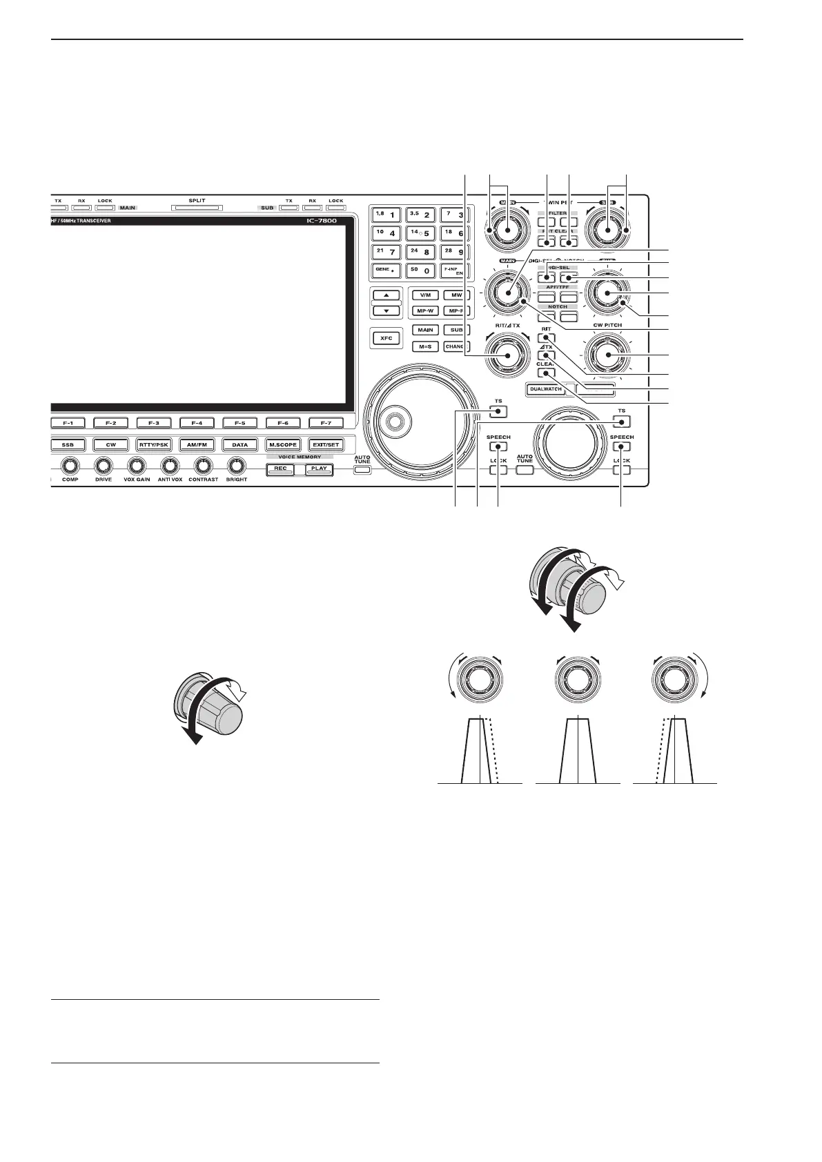
*0 RIT/∂TX CONTROL [RIT/∂TX] (pp. 5-11, 6-4)
Shifts the receive and/or transmit frequency without
changing the transmit and/or receive frequency.
•Rotatethecontrolclockwisetoincreasethefrequency,
or rotate the control counterclockwise to decrease the
frequency. The RIT or ∂TX functions must be ON.
•Theshiftfrequencyrangeis±9.999kHzin1Hzsteps
(or ±9.99 kHz in 10 Hz steps).
Frequency
increases
Frequency
decreases
*1 PASSBAND TUNING CONTROLS [TWIN PBT]
(for MAIN band; p. 5-13)
*2 PASSBAND TUNING CONTROLS [TWIN PBT]
(for SUB band; p. 5-13)
Adjusts the receiver’s IF filter “passband width” via
the DSP.
•Passbandwidthandshiftfrequencyaredisplayedinthe
multi-function display.
•
Hold down [PBT CLEAR] for 1 second to clear the PBT
settings.
•Theadjustment rangeishalfofthepassbandwidth,
and the value is adjustable in 25 Hz steps for the SSB/
CW/RTTY/PSK modes, and 100 Hz steps for the AM
mode.
✔ What is the PBT control?
The PBT function electronically modifies the IF passband
width to reject interference. This transceiver uses the DSP
circuit for the PBT function.
PBT2
PBT1
Low cutHigh cut Center
–+
*3 PBT CLEAR SWITCH [PBT CLEAR]
(for MAIN band; p. 5-13)
*4 PBT CLEAR SWITCH [PBT CLEAR]
(for SUB band; p. 5-13)
Clears the PBT settings when held down for 1 sec-
ond.
•The [PBT CLEAR] indicator above this switch lights
when PBT is in use.
1
PANEL DESCRIPTION
8
*3*1 *2*4
*8
*7
*9
(0
(2
(3
(4
*6
*5
(1