29
6. Operating States and Operation
6.1. Operating Concept
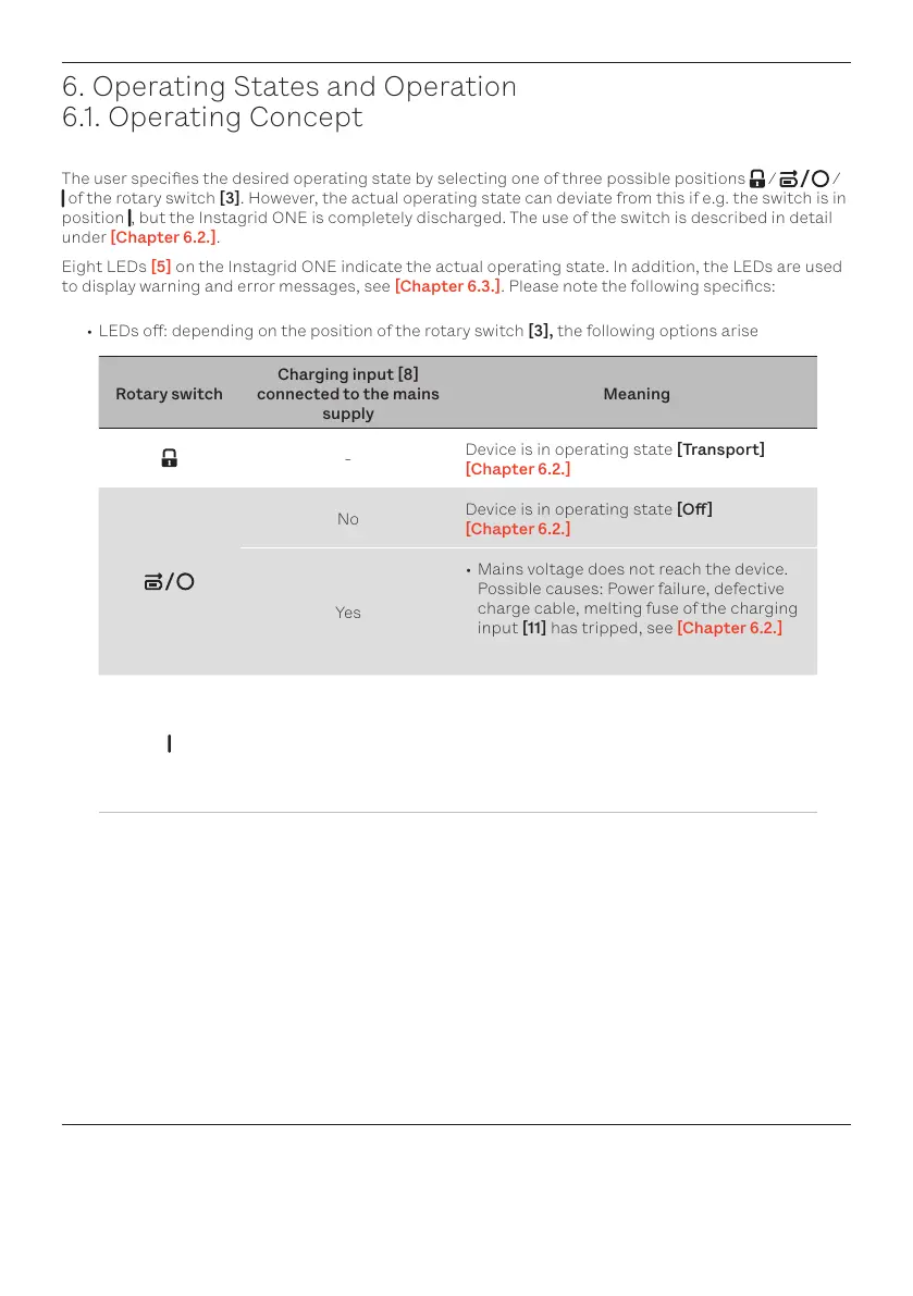
The user species the desired operating state by selecting one of three possible positions / /
of the rotary switch [3]. However, the actual operating state can deviate from this if e.g. the switch is in
position , but the Instagrid ONE is completely discharged. The use of the switch is described in detail
under [Chapter 6.2.].
Eight LEDs [5] on the Instagrid ONE indicate the actual operating state. In addition, the LEDs are used
to display warning and error messages, see Chapter 6.3.. Please note the following specics:
• LEDs o: depending on the position of the rotary switch [3], the following options arise
Rotary switch
Charging input 8
connected to the mains
supply
Meaning
-
Device is in operating state [Transport]
[Chapter 6.2.]
No
Device is in operating state [O]
[Chapter 6.2.]
Yes
• Mains voltage does not reach the device.
Possible causes: Power failure, defective
charge cable, melting fuse of the charging
input [11] has tripped, see [Chapter 6.2.]
• LED display possibly defective
-
• Energy accumulator completely discharged
• A warning or error has occurred during
use in operating state [Discharging], see
Chapter 6.3.
• LED display possibly defective
• LEDs show a pulsating animation in white: the internal control electronics passes through a start-
ing sequence with self-diagnosis functions
• One or several LEDs are lit or ash yellow: [Alarm], see [Chapter 6.3.1.]
• One or several LEDs are lit or ash red: [Error], see [Chapter 6.3.2.]
• In the operation states [Charging] and [Discharging] [Chapter 6.2.], the current charge state of
the Instagrid ONE is indicated by the number of LEDs that are permanently lit in green.
• Each LED segment corresponds to a charge of 12.5%