7-9
PERIPHERAL SUBSYSTEM
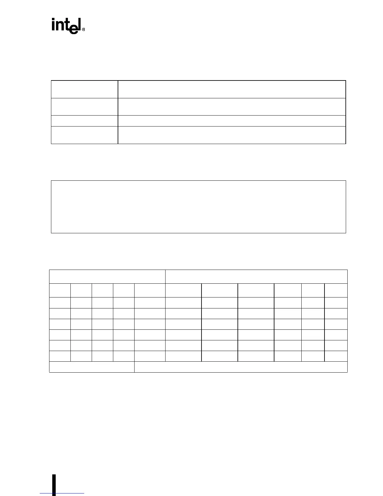
Table 7-3. PLD Input Signals
BS8# The signal is from an 8-bit device or from the system logic that interfaces to an 8-bit
device.
BE3#–BE0# When processor drives all of these signals Low, external logic should look only for
BE0# while in 8-bit mode.
ADS# An address strobe from the Intel486™ processor indicates a valid processor cycle.
OUTPUTS BEN8H#,
BEN8UH#, BEN8UL#
Byte enables for 8-bit interface.
Table 7-4. Equations
BEN8H = ADS * BE1 * /BE0 * BS8
+ /ADS * BEN8H
;Swapping second byte for 8-bit
interface
BEN8UL = ADS * BE2 * /BE1 * /BE0 * BS8
+ /ADS * BEN8UL
;Swapping third byte for 8-bit
interface
BEN8UH = ADS * BE3 * /BE2 * /BE1 * /BE0 * BS8
+ /ADS * BEN8UH
;Swapping fourth byte for 8-bit
interface
Table 7-5. 32-Bit to 8-Bit Steering (Sheet 1 of 2)
Intel486™ Processor
(3)
8-Bit Interface
(1)
BE3# BE2# BE1# BE0# BEN16# BEN8UH# BEN8UL# BEN8H# BHE#
(2)
A1 A0
0000 1 1 1 1 X 0 0
1000 1 1 1 1 X 0 0
0100
†
11 1 1XXX
1100 1 1 1 1 X 0 0
0010
†
11 1 1XXX
1010
†
11 1 1XXX
Inputs Outputs
NOTES:
1. X implies “do not care” (either 0 or 1).
2. BHE# (byte high enable) is not needed in 8-bit interface.
3.
†
indicates a non-occurring pattern of byte enables; either none are asserted or the pattern has byte
enables asserted for non-contiguous bytes.