EMBEDDED Intel486™ PROCESSOR HARDWARE REFERENCE MANUAL
10-8
during switching is supplied by the decoupling capacitors. These capacitors should be placed
close to their devices, as the inductance of lengthier connection traces reduces their effectiveness.
Most popular logic families require that a capacitor of 0.01
µ
F to 0.1
µ
F be placed between every
two to five packages, depending on the exact application. For high-speed CMOS logic, a good
rule of thumb is to place one of these bypasses between every two ICs, depending on the supply
voltage, the operating speed and EMI requirements. The capacitors should be evenly distributed
throughout the board to be most effective. In addition, the board should be decoupled from the
external supply line with a 10 to 47
µ
F capacitor. In some cases, it might be helpful to add a 1
µ
F
tantalum capacitor at major supply trace branches, particularly on large PCBs.
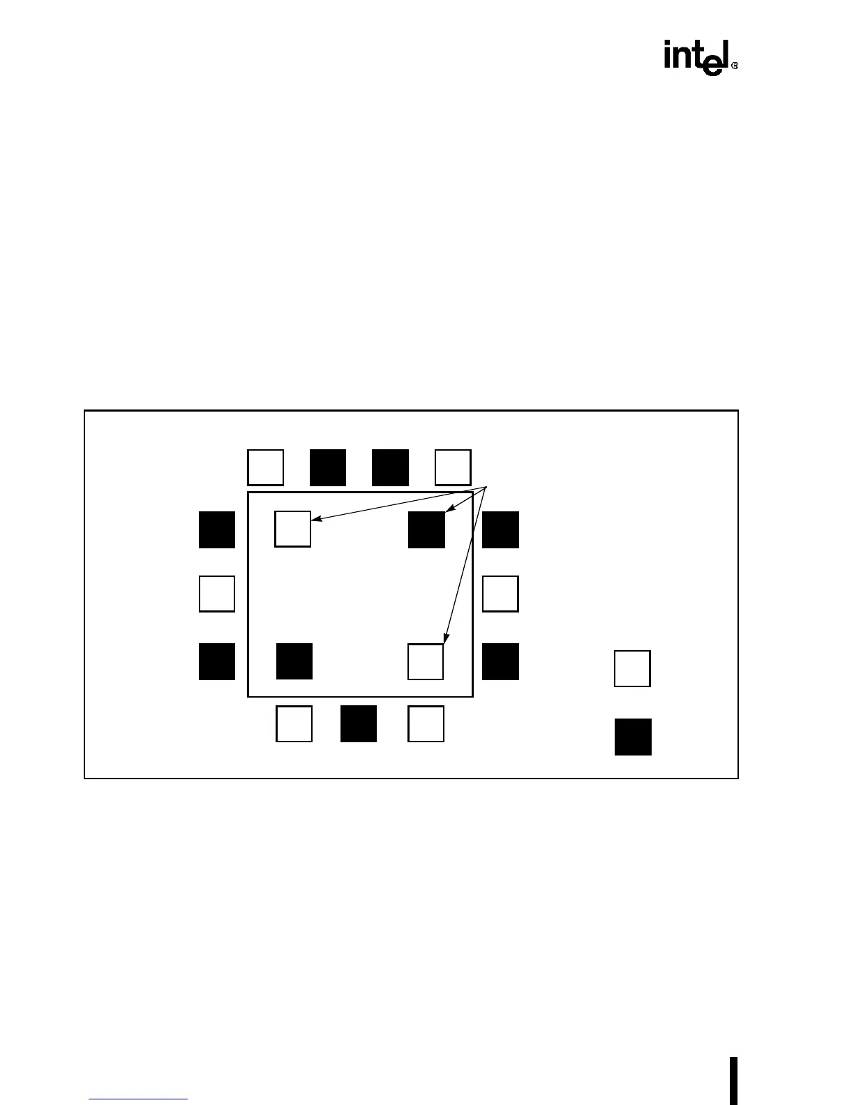
Surface mount (chip) capacitors are preferable for decoupling the Intel486 processor because
they exhibit lower inductance and require less total board space. They should be connected as
shown in Figure 10-5. These capacitors reduce the inductance, which keeps the voltage spikes to
a minimum.
Figure 10-5. Decoupling Chip Capacitors
NOTE
Using Tantalum capacitors allows for smaller capacitance values. Aluminum
capacitors in the same applications should be two to five times larger to
account for aluminum’s higher ESR.
Inductance is also reduced by the parallel inductor relationships of multiple pins. Six leaded ca-
pacitors are required to match the effectiveness of one chip capacitor, but because only a limited
number can fit around an Intel486 CPU, the configuration shown in Figure 10-6 is recommended.
Intel486™
Processor
Under the
Device
= 0.1
µF
= 1.0
µF