3-11
INTERNAL ARCHITECTURE
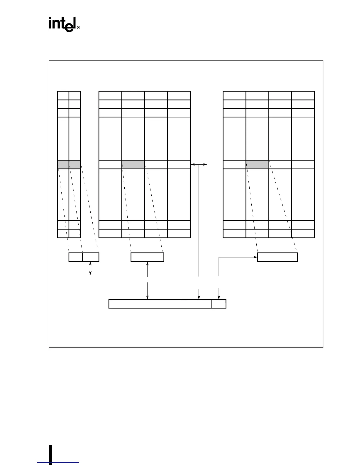
Figure 3-5. Cache Organization
Cache addressing is performed by dividing the high-order 28 bits of the physical address into
three parts, as shown in Figure 3-5. The 7 bits of the index field specify the set number, one of
128, within the cache. The high-order 21 bits (20 on the IntelDX4 processor) are the tag field;
these bits are compared with tags for each cache line in the indexed set, and they indicate whether
a 16-byte cache line is stored for that physical address. The low-order 4 bits of the physical ad-
dress select the byte within the cache line. Finally, a 4-bit valid field, one for each way within a
given set, indicates whether the cached data at that physical address is currently valid.
Way 3Way 2Way 1
Data
Block
Way 0Way 3Way 2Way 1
Tag
Block
A5141-02
Valid/LRU
Block
Way 0
Set N
Set 127
Set 126
Set 2
Set 1
Set 0
ValidLRU Data - 16 bytesTag - 21 bits
†
xxxxIndex FieldTag Field
31 011 4
Physical Address
X 1 X X
line is valid
Index
is N
Match
Selects
byte
†
20 bits for the IntelDX4™ processor