MAINTENANCE MANUAL
INTEL
®
FALCON™ 8+ UAS
DESCRIPTION
66 © 2017 Intel Corporation. All rights reserved.
REV 00
APR 2017
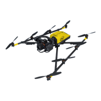
Side view (left):
1) LEDs (red when Intel
®
Falcon™ 8+ UAS
is running), same on the right side
(green when Intel
®
Falcon™ 8+ UAS is
running)
2) Vibration dampers
3) Cable tube, contains the cabling of the
antennas.
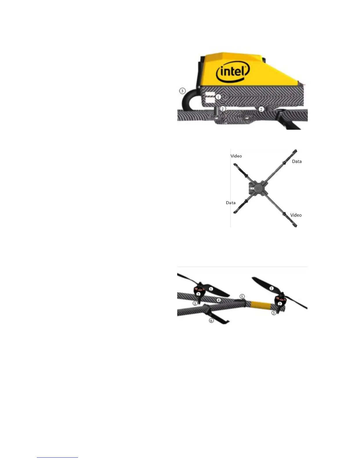
7.1.2 Carbon Cross
The Motor Rails are connected by a carbon cross which
consists of four carbon tubes connected by a center cross
piece.
The data link antennas (2.4 GHz) as well as the video link
antennas (5.8 GHz) are integrated into the landing feet. They
are diagonally arranged.
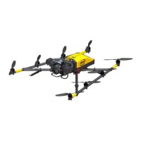
7.1.3 MOTOR RAILS AND PROPELLERS
This Aircraft Flight Manual uses the terms “rotors” and “propellers” interchangeably.
The Motor Rails and the related elements consist of:
1) Propellers, mounted directly on the
Motors
2) Brushless Motors, mounted directly
onto the Mounts
3) Brushless Motor Mount
4) Carbon fiber tube
5) Connector between Center Cross and
Motor Rails
6) Landing Foot
7) Integrated video link antenna
Each Motor Rail consists of four brushless Motor controllers seated within the carbon tube.