DESCRIPTION
© 2017 Intel Corporation. All rights reserved. 95
REV 00
APR 2017
This flight plan can be loaded and executed using the NAVIGATOR function of the Intel
®
Cockpit
GCS application on the touchscreen tablet. At each waypoint an image is triggered, and the
current GPS position is stored in the Intel
®
Falcon™ 8+ UAS log. Images and GPS information can
later be used in photogrammetry software to create orthomosaics, digital surface models or 3D
models.
Please refer to the AscTec Navigator Software manual for detailed information. The manual can
be found at http://www.intel.com/falcondownloads.
CAMERA MOUNT AND GIMBAL
Cameras always remain within their gimbal (camera mount) and the complete gimbal with
camera is exchanged, for which no tools are required. The Intel
®
Falcon™ 8+ UAS automatically
identifies the attached camera, and the menus on the Intel
®
Cockpit GCS are changed
accordingly.
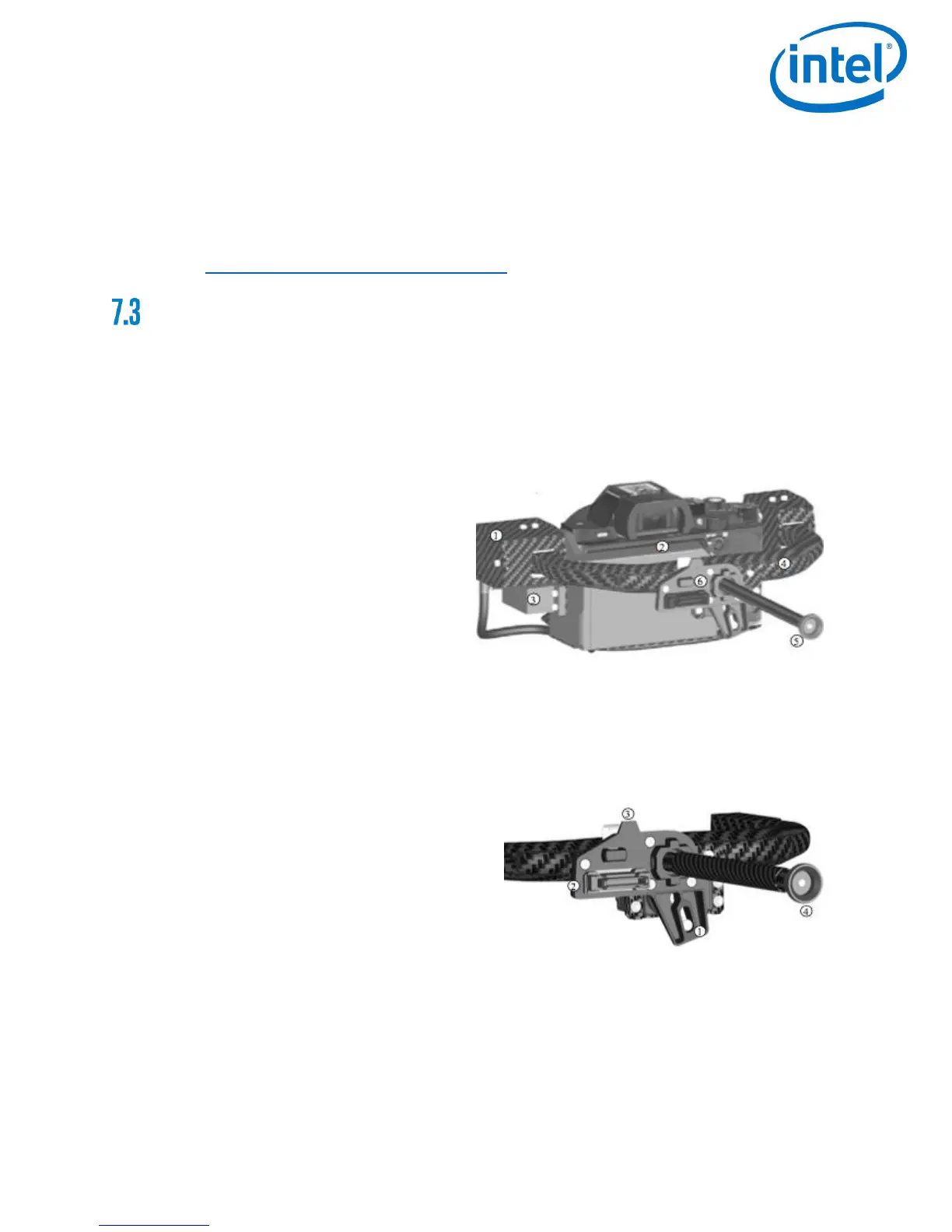
The actively stabilized camera mount consists of:
1) Circuitry for controlling the camera
2) Payload
3) Pitch servo
4) Lightweight Carbon Fiber structure
5) Knurled securing nut for the actively
stabilized camera mount
6) Payload adapter
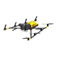
The payload adapter is the connection between the camera mount and the central unit of the
Intel
®
Falcon™ 8+ UAS. It is movable mounted on the rod of the camera mount and connected
to this by a cable.
The payload adapter consists of:
1) Connector plug
2) Adapter slot for the ball link connector of
the roll servo
3) Releasing clip
4) Knurled securing nut for the actively
stabilized camera mount