MAINTENANCE MANUAL
INTEL
®
FALCON™ 8+ UAS
DESCRIPTION
68 © 2017 Intel Corporation. All rights reserved.
REV 00
APR 2017
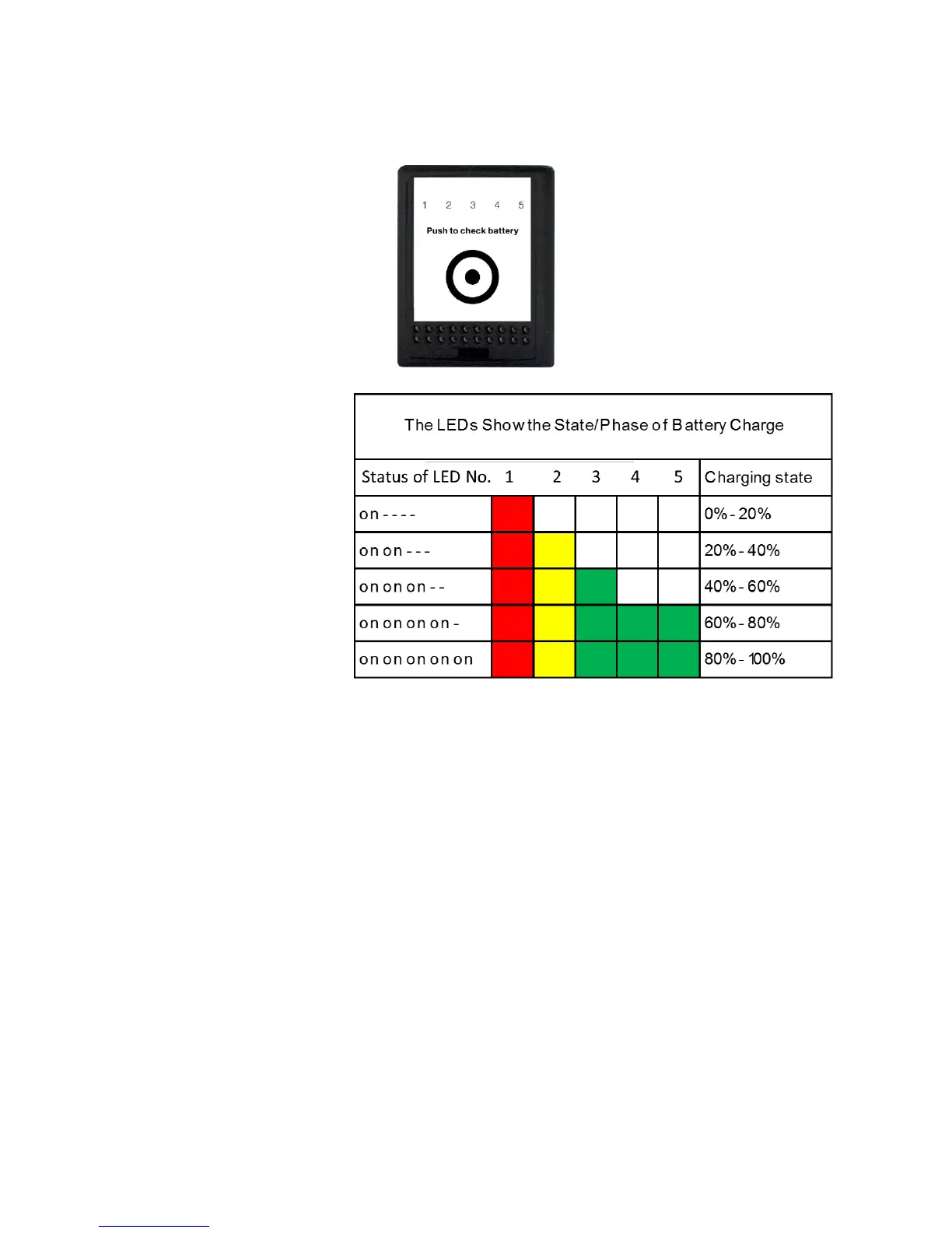
On the front panel of the Intel
®
Powerpack™ Battery, there is a sticker. An area is marked by a
dot surrounded by a circle. This area has the function of a button.
The LEDs are integrated in
the front panel of the Intel
®
Powerpack™ Battery.LED
number / color from left to
right:
1/ red
2 / yellow
3 / green
4 / green
5 / green
One short push (< 2 sec) on the button indicates the charging state of the battery by showing
the respective number of LEDs.
During the charging process (Intel
®
Powerpack™ Battery is connected to the power supply unit
and this to a wall outlet 100 V - 240 V AC 50 Hz - 60 Hz) the actual battery state and the progress
of the charging process is shown by the LEDs automatically.
The number of permanently lighted LEDs shows the progress of the charging process.
If the next higher LED is blinking, this charging step is not yet finished.
When the charging process is finished and the full capacity of the Intel
®
Powerpack™ Battery is
reached, all five LEDs will blink simultaneously if connected for charging.