USER MANUAL
INTEL® FALCON™ 8+ UAS
© 2018 Intel Corporation. All rights reserved 21
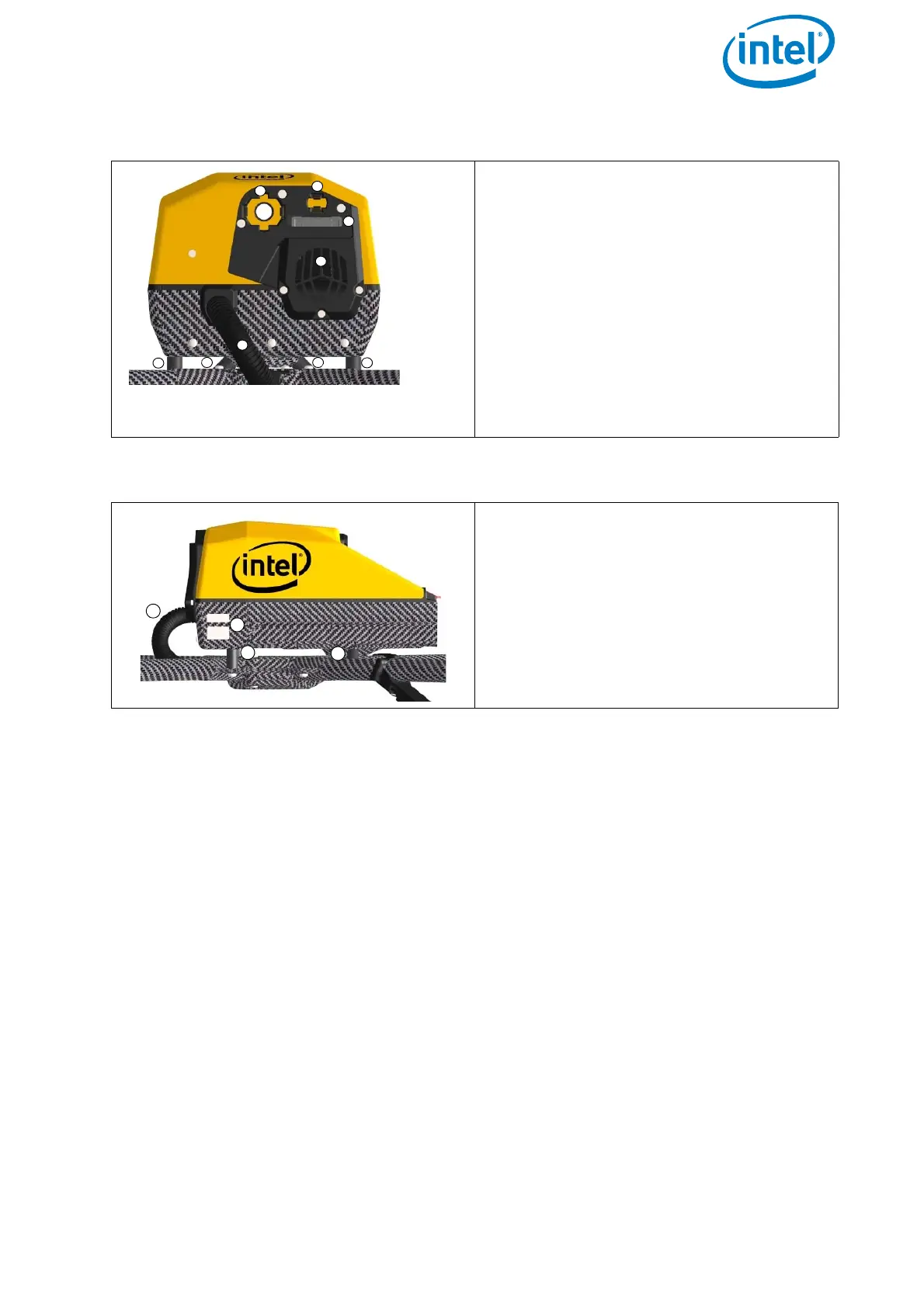
Figure 2.3: Central Unit Front View without Gimbal (Camera Mount)
Front view:
(1) Hole for the camera mount’s carbon
rod
(2) Connector slot for the plug of the
payload adapter, (see no. (1) in “Units
of the Gimbal” on page 23
(3) Retaining clip for the payload adapter
(4) Cable tube (contains the cabling of
the antennas)
(5) Fan for the internal cooling behind
the slots
(6) Vibration dampers
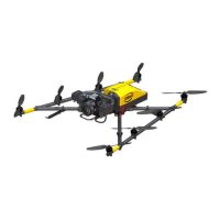
Figure 2.4: Central Unit Side View, Left Side without Gimbal (Camera Mount)
Side view (left):
(1) LED position light (red when UAV is
running), same on the right side
(green when UAV is running)
(2) Vibration dampers
(3) Cable tube (which contains, e.g., the
cabling of the antennas)