USER MANUAL
INTEL® FALCON™ 8+ UAS
© 2018 Intel Corporation. All rights reserved 40
• Keep the airplane mode of the camera switched on, to avoid radio interference
from the camera (MENU > > Airplane Mode > ON).
2.5.3.2. Camera Control By The CTR
This section describes how the Sony Alpha 7R can be operated by using the functional
elements of the CTR.
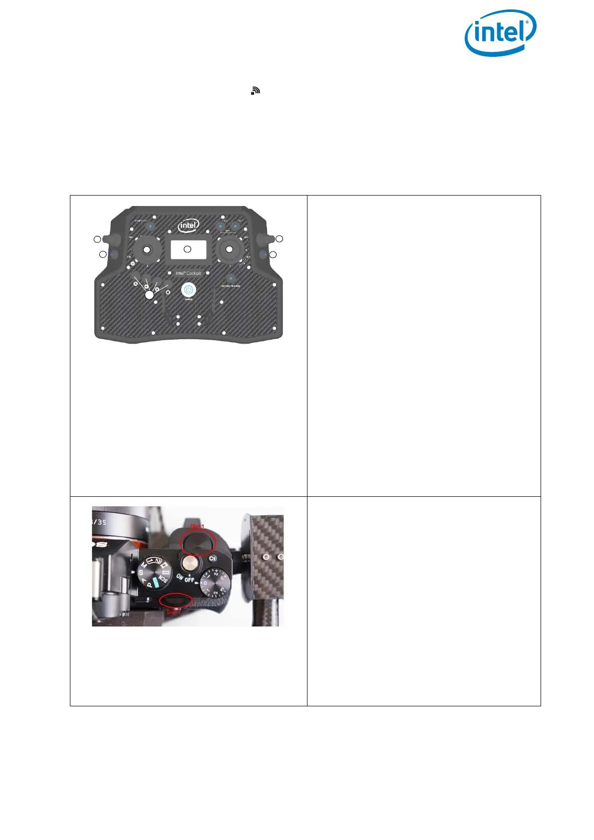
Figure 2.16: Sony Alpha 7R CTR Control Layout
Push Button B1 (1): sets the camera to
predefined angles +/-90°, +/-45° and 0°
when Rocker Switch R1 (4) is pushed
simultaneously (see “Setting the Camera
Angle” on page 33 for details).
Push Button B2 (2): changes the function
depending on the connected payload.
Push Button B3 (3): trigger button
Rocker Switch R1 (4): camera tilt,
changes the angle smoothly.
Rocker Switch R2 (5): camera tilt; Dial 1
or Dial 2, depending on B2
Control Stick S2 (6): turning the right
control stick (S2) controls the yaw axis of
the UAV.
Status Display (7): see “Camera Options
By The Status Display” on page 41
ESC, LEFT, RIGHT, ENT (8): Status Dis-
play control buttons (see “Status Dis-
play” on page 27).
The Sony Alpha 7R has two main func-
tion dials that can be controlled by the
CTR.
The function of Dial 1 on the Sony A7R
can be controlled by R2, when B2 is in
position 1 (LED off). The function of Dial
2 can be controlled by R2, when B2 is in
position 2 (LED on/blue) or via the Status
Display by pushing ENT > Camera
Options > Dial 2
.
The default functions of Dial 1 and 2
depend on the selected shooting mode
on the camera. The table below shows
the dependencies.