ManagerIQEasy_UM_9752103002_GB_V3_1 15
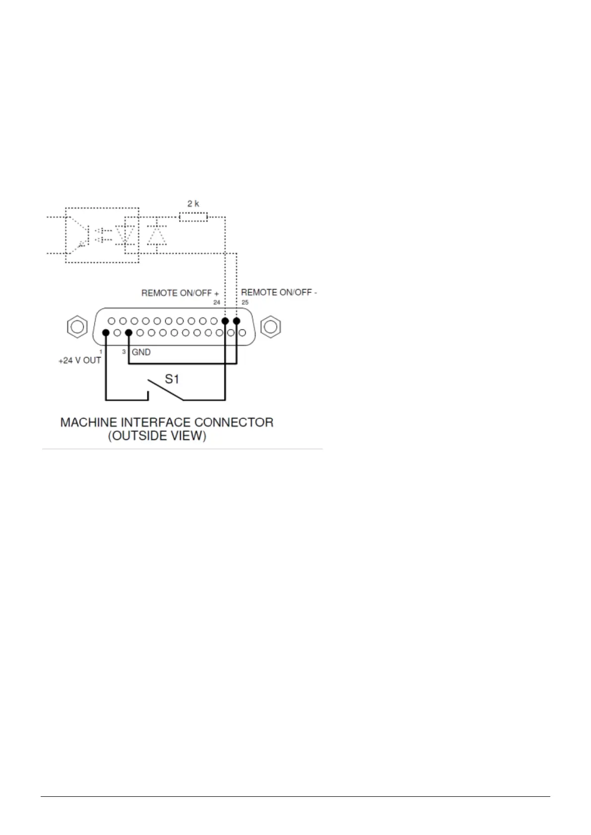
5.4.4.2 Remote on/off input
Each connected Device can be switched via the remote on/off input.
How to connect the Device with this input is explained in the manual of the corresponding
Device (see the “Remote on/off source” parameter, Section 6.6).
- Connect an external 24 V switching signal between pins 24 and 25
(24V = Remote ON, 0V = Remote OFF)
- Or: Use the 24V DC output and connect a potential-free switching contact between pins
1 and 24 and create a connection between pin 3 and 25.
Figure 8, Wiring Remote on/off input on the machine interface connector
5.4.5 Fieldbus connection
With an optional Fieldbus connection (EtherNet/IP, ProfiNet, etc.), controls such as remote
on/off, warnings and alarms can be linked to a machine control (PLC). Setpoint settings and
reading back of readings are also possible when using a (Fieldbus).
For this, a (Fieldbus) interface module is mounted into the Anybus slot at the factory.
For connecting these fieldbuses, follow the general instructions applicable to these fieldbuses.
5.4.6 Ethernet connection
For transmitting datalog data from the Manager IQ Easy to a PC, the manager can be connected
to a network. For wiring, a standard UTP cable with an 8-pole RJ45 connector can be used.
An Ethernet IP address must be assigned by the network (using DHCP).
For retrieving the assigned IP address, see Section 6.17.11.
 Loading...