Section 17 Adjusting and Setting up Equipment (for Services) 17-6
1 Measure the height from the sea surface to the radar antenna.
2 In the [Antenna height] combo box, select the setting value corresponding to the
height of the antenna that was measured in step 1.
• Under 5 m
• 5-10 m
• 10-20 m
• 20 m Over
17.2.4 Adjusting MBS
MBS (Main Bang Suppression) adjustment is to adjust a display unit processing circuit in order to
suppress main bang, which is the reflection signal from a microwave transmission circuit of a
waveguide that normally appears as an image of a circle at the center of the radar screen.
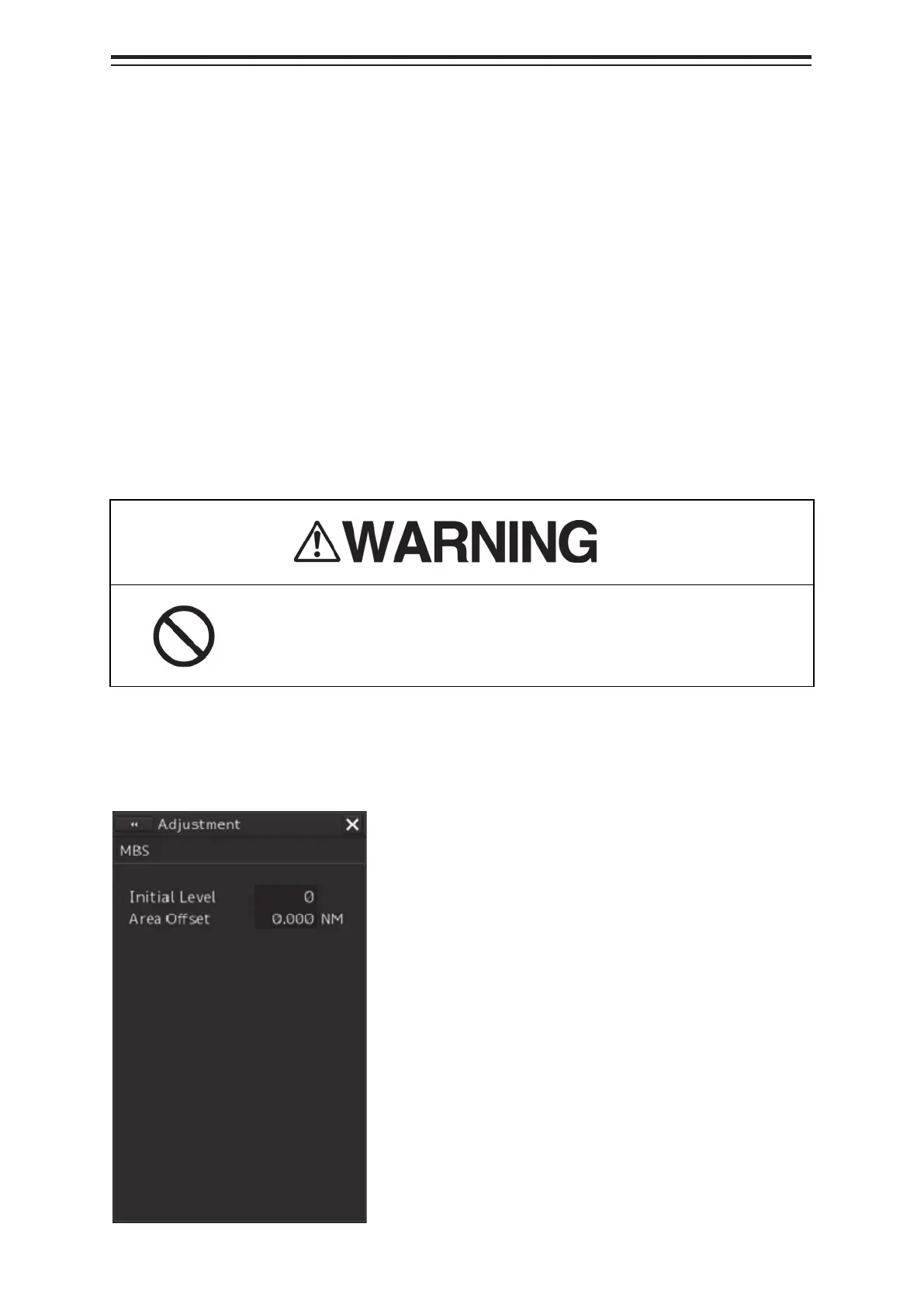
Perform MBS adjustment by using the [MBS] dialog.
Do not change Initial Level/Area Offset unless absolutely necessary.
Incorrect adjustment will result in deletion of nearby target images and
thus collisions may occur resulting in death or serious injuries.
17.2.4.1 Displaying the [MBS] dialog
When you select [MBS] in the classification pane, the [MBS] dialog is displayed in the edit pane.