17-13 Section 17 Adjusting and Setting up Equipment (for Services)
1
2
3
4
5
6
7
8
9
10
11
12
13
14
15
16
17
18
20
21
22
23
24
25
APP A
APP B
Setting a serial port on the CCU
Set each item as follows.
"Table A: Sensors that can be selected by serial ports on CCU" shows selectable sensors.
However, the sensors that actually can be selected vary depending on the equipment setting.
For the sensor communication speed, refer to "Selectable baud rates".
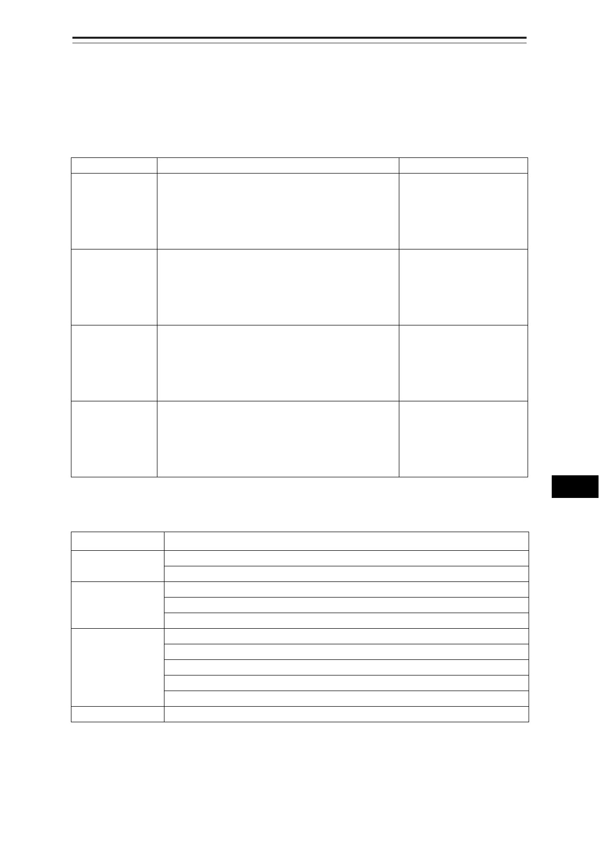
Setting Item Description of Setting Setting Value
Gyro 1. Select the check box and enable the serial port for the
Gyro.
2. Select a sensor to be connected to the serial port for
Gyro from the [Sensor] combo box. When not
selecting a sensor, set [ - ].
To enable: Select.
To disable: Clear.
LOG 1. Select the check box and enable the serial port for the
LOG.
2. Select a sensor to be connected to the serial port for
LOG from the [Sensor] combo box. When not
selecting a sensor, set [ - ].
To enable: Select.
To disable: Clear.
GPS 1. Select the check box and enable the serial port for the
GPS.
2. Select a sensor to be connected to the serial port for
the GPS from the [Sensor] combo box. When not
selecting a sensor, set [ - ].
To enable: Select.
To disable: Clear.
AIS 1. Select the check box and enable the serial port for the
AIS.
2. Select a sensor to be connected to the serial port for
the AIS from the [Sensor] combo box. When not
selecting a sensor, set [ - ].
To enable: Select.
To disable: Clear.
Table A: Sensors that can be selected by serial ports on CCU
Serial port Sensor name
Gyro Heading Sensor(NMEA), Heading Sensor1(NMEA)
*1
, Heading Sensor2(NMEA)
*1
Heading Sensor(Gyro I/F), Heading Sensor1(Gyro I/F)
*1
, Heading Sensor2(Gyro I/F)
*1
LOG Log(NMEA), Log1(NMEA)
*2
, Log2(NMEA)
*2
Log(Gyro I/F)
*3
Selector
GPS GPS 1
GPS 2
*4
GPS 3
*4
GPS 4
*4
Selector
AIS AIS
*1: Only when two heading sensors are available.
*2 : Only when two logs are available
*3 : Only when Heading Sensor(Gyro I/F) is selected for Gyro of CCU
*4 : May not be displayed depending on the number of GPS units