Section 17 Adjusting and Setting up Equipment (for Services) 17-12
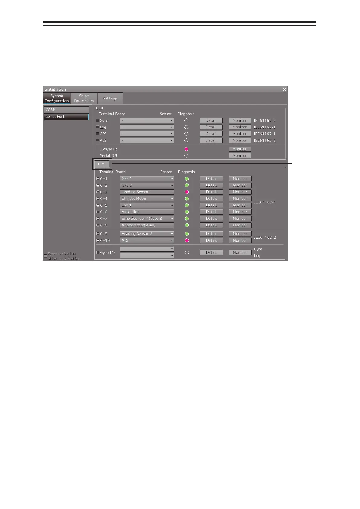
17.3.3.1 Displaying the [Serial Port] dialog
When you select [System Configuration] in the first classification pane and [Serial Port] in the second
classification pane, the [Serial Port] dialog is displayed in the edit/result pane.
17.3.3.2 [Diagnosis] lamp light colors
The [Diagnosis] lamp indicates the Diagnosis result on whether or not the sentence of the sensor
specified for each serial port has been received successfully and the status of ISW/MTR/Serial OPU.
Lit in red: Data not received.
Lit in green: Data is receiving.
Lit in orange: In Diagnosis (before decision).
No color: Serial port is disabled.
17.3.3.3 Setting a serial port
In the [Serial Port] dialog, allocate the sensors to be connected for the serial port on CCU (Central
Control Unit) and the serial port on SLC/ALC.
Tab name
display