B-151 Appendix B Menu List and Materials
1
2
3
4
5
6
7
8
9
10
11
12
13
14
15
16
17
18
19
20
21
22
23
APP B
24
25
27
APP C
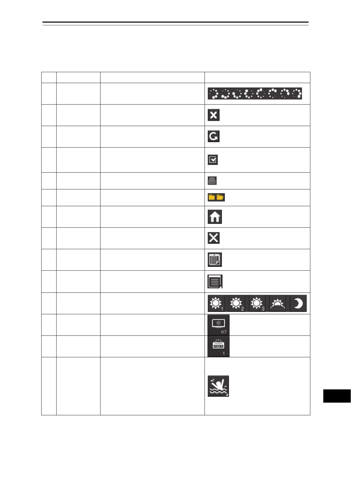
B.9 List of Icons/Icon Buttons
The icons/icon buttons displayed in this equipment are listed below.
No. Name Functional outline Displayed image
1 Active
indicator
Indicates that the computer is
processing by an animation.
2 Delete Deletes the item.
3 Check again Checks the contents being displayed
again.
4 Setting mark Displayed when the operation is valid.
(E.g., Latitude and longitude offset of
chart)
5 Drive Displayed at the left of the name
when a drive is selected.
6 Folder Displayed at the left of the name
when a folder is selected.
7 Home Changes from the currently displayed
screen to the home screen.
8 Close Closes the dialog box.
9 Date selection Displays the calendar picker.
10 Dialog box
display
Opens another dialog box. (E.g.,
Route selection dialog)
11 Day/Night Displays the state of the current
Day/Night setting by an icon.
12 Screen
brightness
Enables adjustment of the screen
brightness.
13 Panel
brightness
Enables adjustment of the brightness
of operation unit.
14 MOB Starts the MOB (Man Over Board)
mode.
In the MOB mode, a symbol display of
the position of the sailor falling over
board and a dotted like connecting it
to the own ship are displayed
graphically.