4 – 3
Procedures
1. Press the
EBL
key and select display and motion of EBL1.
(See subsection “3.3.2 Using EBL (Electronic Cursor) [EBL]”.)
EBL1 on the lower left is displayed in a box and EBL1 is displayed by a short dashes
line on the PPI screen.
2. Turn the EBL control and bring EBL1 to a target.
The bearing of EBL1 is displayed on the lower left of the screen.
The bearing of EBL1 is the one of the target.
3. Press the
VRM
key and select display and motion of VRM1.
(See subsection “3.3.12 Displaying Variable Range Markers [VRM]”.)
VRM1 on the lower left of the screen is displayed in a box and VRM1 is displayed by
a short dashes line on the PPI screen.
4. Turn the VRM control to bring VRM1 indicated by a short dashes line to a
target.
The range of VRM1 from the own ship is displayed on the lower left of the screen.
The range of VRM1 is the one from the own ship to the target.
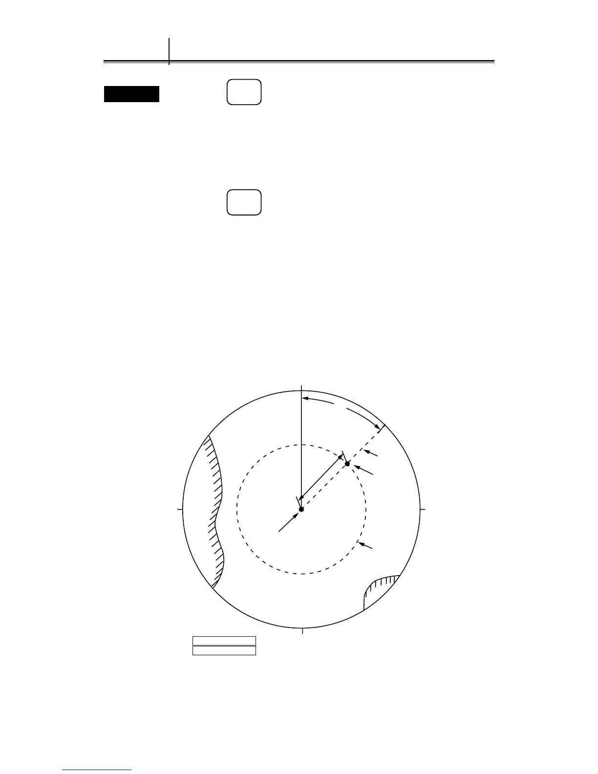
See Fig. 4.2, in which the range from the own ship to the target and the bearing are as
follows: Range: 4.0nm, Bearing: 45.0°
90270
EBL1
Target
Own ship
4.0NM
45°
0
180
VRM1
45.0° R
4.000NM
EBL1
VRM1
Fig. 4.2
4.3
Measurement with Electronic Cursor and Variable Range Marker
 Loading...