7 – 3
7.1
7.1.2.2 Key Switch Test
This test is used to check the operating status of each knob/switch.
Procedures
1. Follow procedures 1 to 3 in subsection 7.1.2.1.
The DIAGNOSTIC MENU appears.
2. Press the
2
key to open the KEY SWITCH TEST menu.
3. Press controls or keys according to the menu item to check them.
They normally operate if the numeral displays change. "255" is displayed when the
control is turned to the maximum and "0" when to the minimum.
4. Press the
0
key.
Exit
5. Press the
SUB
MENU
key.
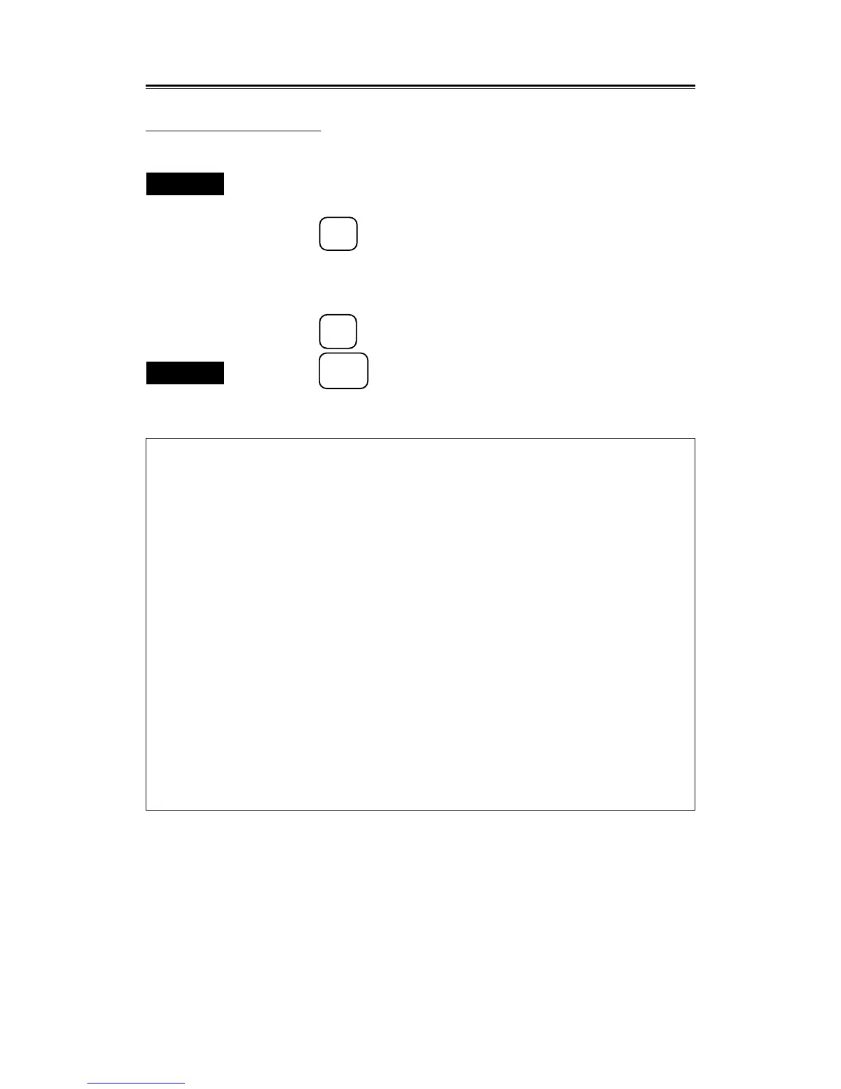
Key Switch Test
KEY SWITCH TEST
0. PREVIOUS MENU
KEY xxxxx
TRACK BALL X 42
Y38
VOLUME GAIN 255
TUNE 126
STC 0
FTC 0
BRILL 250
SHAFT ENCODER EBL 0
VRM 255
ROTARY SWITCH PNK
18
DIPSW1 0 0 0 0 0 0 0 0
DIPSW2 0 0 0 0 1 0 0 0
To close this menu, Press (SUB MENU) key.
 Loading...