Installation Page: 49 Overview Importance of proper installation for radar performance and maintenance, including cable options.
Power Cable Installation Instructions for installing the 3m power cable to the display unit, including wire colors and voltage.
Ensuring View Angle Minimizing blind sectors and ensuring adequate view angles for optimal radar coverage.
Various Functions Page: 102 Vector Length Setting the vector length for own ship and other targets to indicate predicted movement.
Radar Trails Function for displaying radar trails to help assess navigation and bearing maintenance.
AIS Operations Displaying target information from AIS, including ship name and data.
TT Operations Using the target tracking function to calculate target course and speed, and alarm for collision risks.
Off-Center Function Moving the own ship's display position to observe areas outside the screen radius.
Mark Function Indicating marks on the screen, which store latitude and longitude information.
Line Function Drawing lines on the radar screen to indicate positions and holding latitude/longitude.
User Option Keys Assigning menu shortcuts to USER1 and USER2 buttons for quick access to frequently used menus.
Mode Function Switching between different radar video modes for various observation scenarios.
Cursor Function Displaying information about the cross cursor, including distance, direction, and arrival time.
Radar Echo Setting Adjusting radar image settings like pulse width, IR, target enhance, process, zoom, and video settings.
Pulse Width Changing the transmitter pulse width to optimize range resolution and clutter suppression.
Target Enhance Enhancing target video display by enlarging echo areas for better visibility.
Process Reducing unnecessary noise to highlight targets, suitable for TM mode.
Zoom Mode Zooming in on the radar video display for closer inspection of targets.
Video Latitude Selecting the dynamic range for displaying receiving signals based on weather conditions.
Tune Using automatic or manual tuning modes to optimize transmission and receiving frequencies.
Marker Setting operations for EBLs, parallel cursors, cursor mode, and range rings.
EBL Setting Setting the mode to move the starting point of EBLs and the bearing fix mode.
Parallel Cursor Setting parallel cursors for range scale link, floating, bearing fix mode, and display options.
VRM Unit Setting the unit for Variable Range Markers (VRM) to NM, km, sm, or Link Range.
Cursor Mode Setting cursor display details: bearing mode, length, unit, and pattern.
Range Ring Setting the display of range rings on the radar screen.
Trails Setting Setting radar trails parameters: threshold, time/all combine, and trails mode.
Vector Setting TT and AIS vector parameters: vector mode and own ship vector display.
Offcenter Setting Moving the own ship's display position to any point within 66% of the screen radius.
Function Setting Storing and recalling optimal radar video settings for various conditions.
AIS;TT Information on AIS operations, collision avoidance concepts, and TT operations.
Guard Zone Setting up guard zones to detect target movement and sound alarms.
Chart Setting the display of charts, including type, display on/off, symbols, and palette.
Mark Setting Setting the size, color, and type for marks on the radar screen.
Line Setting Setting the colors and types for lines drawn on the radar screen.
Own Track Setting Configuring own ship's track recording, display, color, type, and interval.
File Operation Managing marks, lines, and own tracks stored in the equipment via USB.
Screen Capture Using the screen capture function to save images to USB memory.
Timed TX Reducing power consumption by alternating between TX and standby states.
Initial Settings Page: 182 Language Selection Procedure to select the display language, with instructions to return to English.
Range Adjustment Adjusting the radar range to match known target ranges and VRM readout data.
Tuning Adjustment Fine-tuning receiver circuits for maximum sensitivity to transmitted signals.
Baud Rate Setting the data speed for communication, including automatic switching.
Rx Sentence Selecting which sentences to receive from external devices like GPS, Heading, and Depth.
Rx Port Choosing the receive port for signals such as CAN, GPS, NMEA, and Gyro Compass.
Tx Port Selecting the transmit port for signals such as TTM, TLL, and NMEA.
Tx Data Format Setting the NMEA format for data transmission from the transmission port.
I;F Device Making settings for equipment connected for true bearing signals, data, and speed.
Heading Equipment Selecting the input source for heading data: manual, GYRO/Compass, or GPS.
Manual Heading Manually inputting heading direction value when manual input is selected.
Speed Equipment Selecting the input source for speed data: GPS, Log/2axis Log, or manual.
Manual Speed Manually inputting speed value for internal processing and radar trail/vector adjustments.
JRC GPS Settings for JRC GPS receivers, including NMEA version and GPS settings.
NMEA Version Setting the NMEA version for output GPS sentences, or auto-detection.
GPS Setting Configuring GPS settings: correction method, fix mode, elevate mask, HDOP, smoothing, and exclusion satellites.
Beacon Setting Setting the frequency and baud rate for JRC Beacon (DGPS receiver) manually or automatically.
SBAS Setting Automatically or manually selecting the SBAS satellite number for enhanced GPS accuracy.
LORAN Setting Setting up LORAN parameters, including time zone and chain selection.
Detail Performance Settings Page: 200 Radar Echo Adjusting radar echo settings: noise level, main bang suppression, target enhance, gain, sea, and rain.
Noise Level Adjusting the noise level, with fine-tuning recommended after initial factory settings.
Main Bang Suppression Adjusting main bang suppression to reduce reflection signals from the radar display center.
Target Enhance Level Setting target enhancement levels to enlarge video display and improve target visibility.
Gain Adjusting minimum sensitivity level of the GAIN control; avoid careless changes.
Sea Setting the STC Curve for sea clutter suppression; avoid changing offset and slope correction.
Rain Setting the FTC Curve for rain/snow clutter suppression; avoid changing offset and slope correction.
Trails Setting radar trails parameters: suppression distance, max interval, and range limit.
Target Tracking (TT) Setting parameters for target tracking: vector constant, gate size, and gate display.
Scanner Adjusting scanner settings: slope correction, PRF fine tuning, stagger trigger, rotation speed, PRF mode, safety switch, tune.
Control Adjusting function buttons and controls: multi control menu timeout, cross key gain, trackball control.
Buzzer Adjusting the buzzer volume and setting external buzzer status.
Maintenance Performing maintenance tasks: reset partial, master reset, system time clear, scanner time clear, table update, internal setting, USB format.
Reset Partial Initializing specific settings like RADAR Echo, Function Setting, Basic Adjustment, Main Menu, etc.
Master Reset Initializing the entire memory area to factory settings; recommended to save settings first.
Scanner Time Clear Saving and restoring scanner time data, useful after replacing internal control circuits.
Table Update Uploading data like STC Curve, Color, Initial Value, etc., to restore settings.
System Setting Setting system boot parameters, displayed units, own ship outline, and radar range.
Display Screen Setting the display screen color, including standby numeric display, day/dusk/night modes.
Error Alarm Mask Setting whether to display or mask detected errors and alarms on the screen.
Network Network function for display and operation with multiple units (not currently implemented).
CAN Setting CAN (Controller Area Network) for radar display unit communication.
Specifications Page: 265 Scanner Dimension Detailed dimensions for various scanner units: NKE-2043, NKE-2063A/AHS, NKE-2103-4/4HS, NKE-2103-6/6HS.
Equipment Outline Overview of the marine radar equipment, including configuration, features, and radar models.
General Specifications General specifications covering display, range scale, resolution, accuracy, and environmental standards.
Scanner Specifications for scanner units: NKE-2043, NKE-2063A/AHS, NKE-2103-4/6/4HS/6HS.
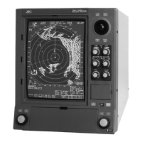
Display Specifications for the integrated display unit (NCD-2364), including structure, dimensions, and functions.
Option Cable Information on available option cables, including lengths and types.