Chapter 1 INSTALLATION
1
Chapter 1 INSTALLATION
1.1 OVERVIEW
The proper installation of the radar equipment is critical in ensuing its effective and reliable performance as
well as facilitating maintenance and repair. Carefully install the radar equipment by following the procedures
below.
z Considering the weight of the scanner unit and install it in a high place as possible.
z It is preferable to install the display unit in the wheel house to facilitate observations.
z Available cable lengths and types for installing the radar JMA-3400 are as shown in the table
below. Request an appropriate cable from JRC beforehand.
A cable longer than the sufficient length may degrade radar performance, so give it careful
consideration when planning the installation.
All installation cable is option.
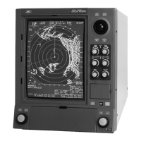
Installation Cable
(Option)
H-CFQ-6912-5 5m
H-CFQ6912-10 10m
CFQ-6912-15 15m
H-CFQ6912-20 20m
H-CFQ6012-30 30m
Installation cable
(option)
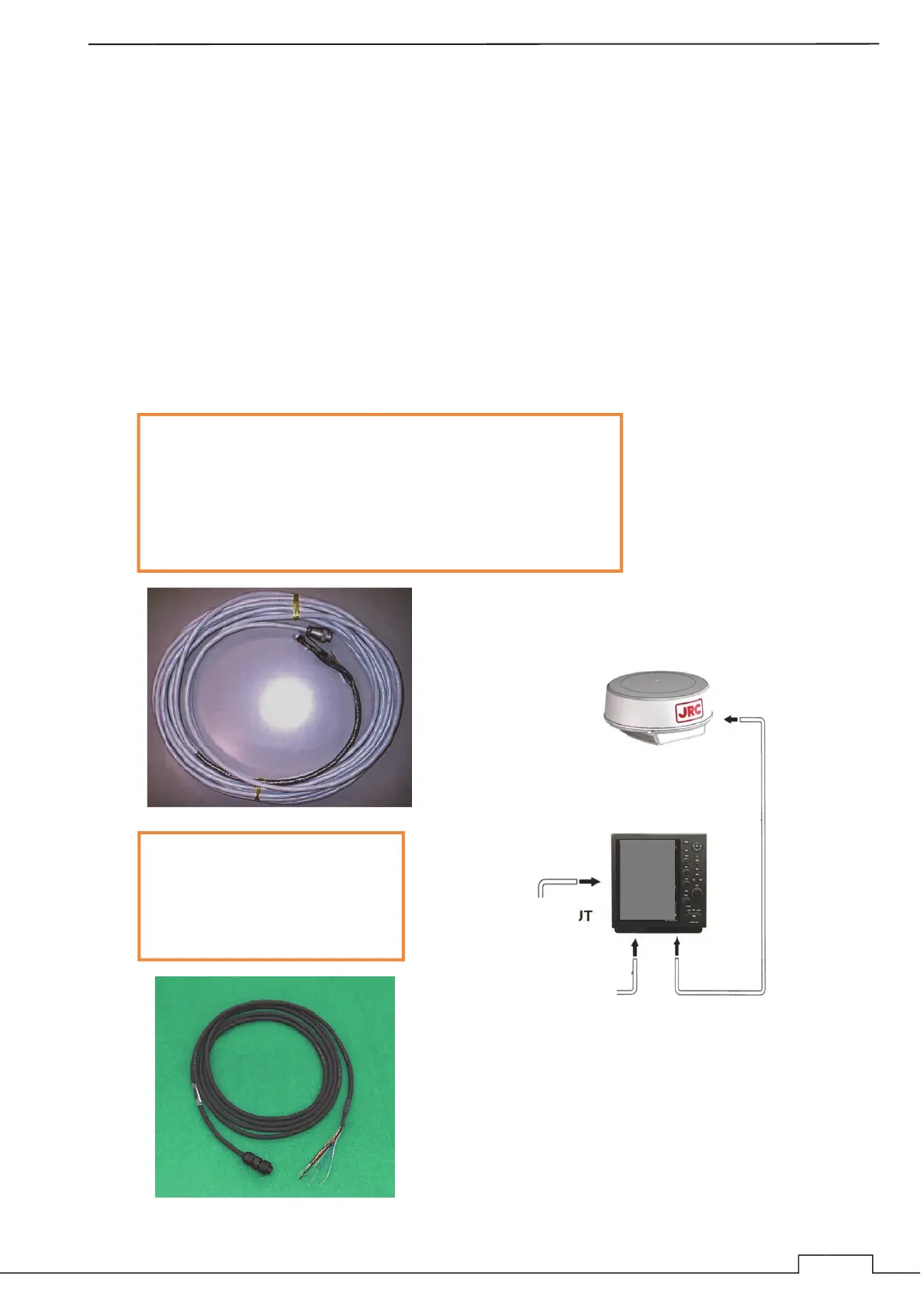
EXTERNAL SIGNAL INPUT
POWER INPUT 12V/24V
Power Supply Cable
Type Name: CFQ-7758
Length: 3m
Standard Supply
INSTALLATION CABLE (Option)
Connect the arrows in the diagram.
(For inputting external signal, optional NMEA cable is
required. Refer to chapter 1.2.6.)
The input voltage is
determined by the RADAR model name.

 Loading...