Chapter 1 INSTALLATION
1.2.5 POWER CABLE INSTALLATION
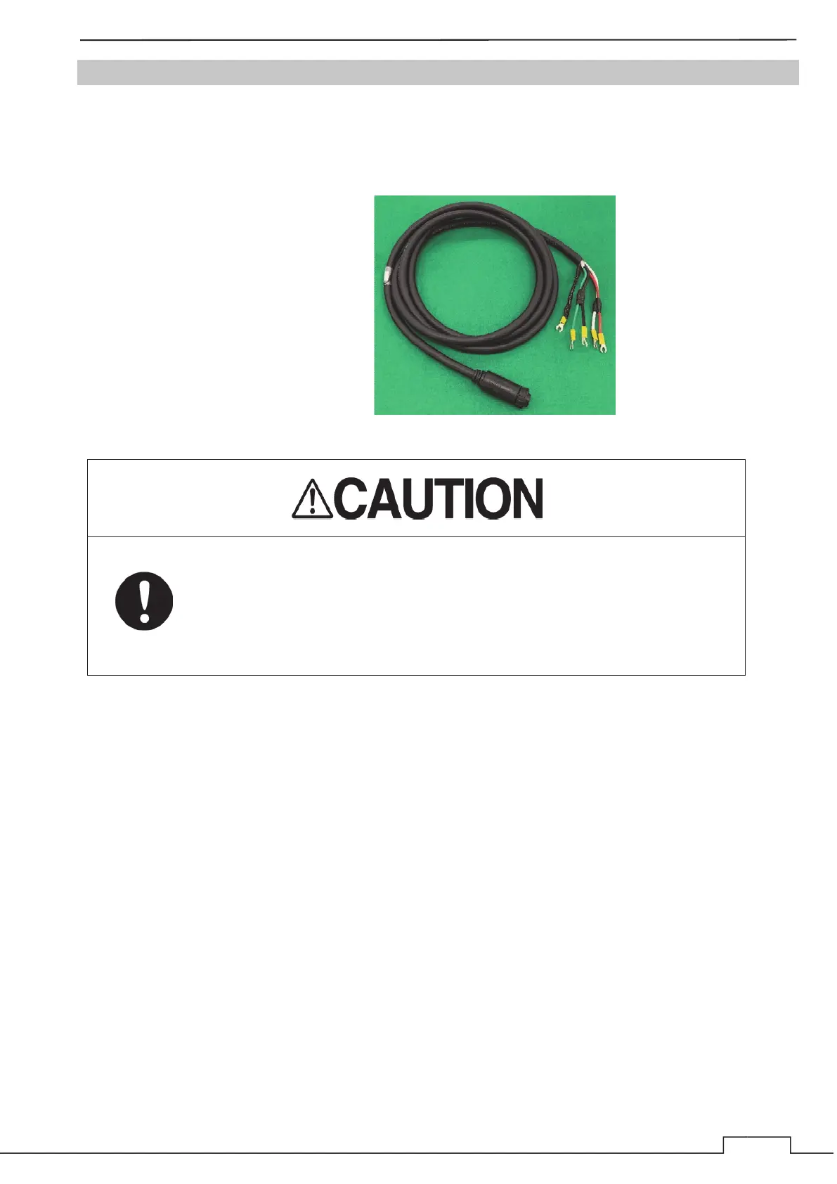
This equipment includes a 3m power cable for power supply to the display unit.
Cable assembly name: CFQ-7758
The cable core wire color is red/white (+), black/green (-) and shield mesh (frame ground).
Wire : AWG12
Red/White: +12/24V
Black/Green: 0V
Shield: FG (frame ground)
Note: Use a rectifier if necessary.
When you connect with the ship power supply without using the optional
rectifier, you need measure the voltage between the ground and the positive
/ negative side of the ship power supply.
When the ship power supply is more than 38V, please take through measures
such as attaching a rectifier.
If you connect to the ship power supply directly without taking any
measures, there is a risk of system failure or accident occur.
Ŷ Power Cable Installation
Connect the power cable (CFQ-7758) to the power input connector of display unit. At that time, please
turn to the right the tip locking mechanism to lock the position of the connector.
CF
-7758

 Loading...