Chapter 5 VARIOUS FUNCTIONS
5.21 VECTOR
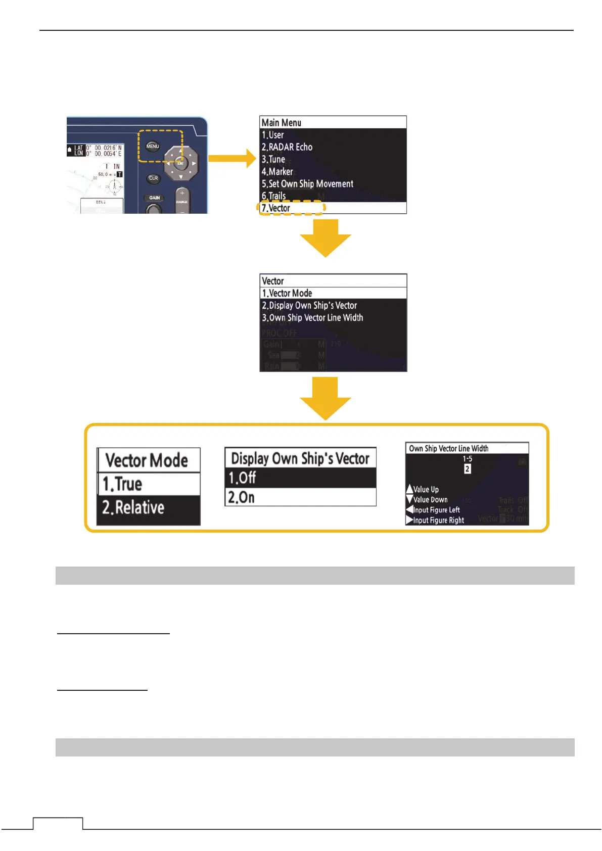
Set TT and AIS vector settings. The bearing and speed signal input are required to display TT and AIS vectors.
To display the vector, you need to input the direction and speed signal.
5.21.1 VECTOR MODE
Set the bearing mode of TT and AIS vectors.
In the True vector mode, the direction of a target vector indicates the true course of the target and its vector
length is proportional to its speed. In this mode, the movements of other ships around own ship can be
accurately and easily monitored.
The relative vector does not represent the true motion of the target, but its relative relation with own ship. This
means that a target with its relative vector directed to own ship will be a dangerous target.
5.21.2 DISPLAY OWN SHIP’S VECTOR
Turn on/off own ship vector display.
Display Own Ship’s Vector
䐡 Select each menu.㻌
Vector Mode
䐟 Press the MENU button.㻌䐠 Select the “Vector.”㻌
Own Ship Vector Line Width
 Loading...