1
Chapter 9 TRUE OR FALSE EHOS ON DISPLAY
9.4.4 FALSE ECHO BY MULTIPLE REFLECTION
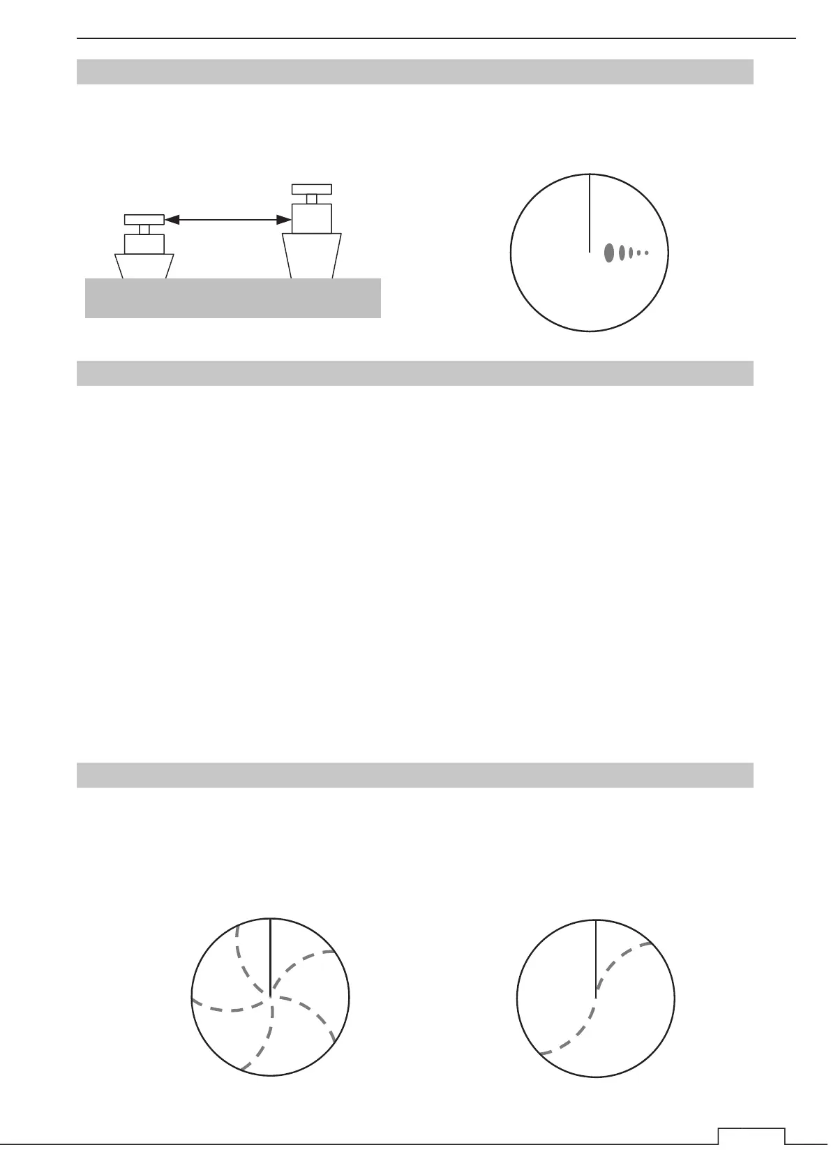
When there is a large structure or ship with a high vertical surface near own ship as shown in Fig. 9-4-4-
1, multiple refection returns may appear on the radar display. These echoes appear in the same
intervals, of which the nearest echo is the true echo of the target.
Fig. 9-4-4-1
9.4.5 SECOND TIME ECHOES
The maximum radar detection range depends upon the height of the scanner and the height of a target
as described in the Section "9.1 RADAR WAVE WITH THE HORIZON". If a so-called "duct" occurs on
the sea surface due to a certain weather condition, however, the radar beam may propagate to an
abnormally long distance, at which a target may be detected by the radar.
For instance, assuming that the pulse length is MP3 (on the repetition frequency of 1400 Hz), the first
pulse is reflected from a target at about 58 NM or more and received during the next pulse repetition
time. In this case, a false echo (second time echo) appears at a position that is about 58 NM shorter
than the actual distance. If the false echo appears at 5 NM on the radar display, the true distance of the
target is 5+58=63 NM. On the pulse length is SP1 (on the repetition frequency of 2250 Hz), a false
echo may appear at a position that is about 36 NM shorter than the actual distance.
This type of false echo can be discriminated by changing over the range scale (the repetition
frequency), because the distance of the target changes accordingly.
If second time echo is appeared, the use of Economy mode in PRF menu is effective. Otherwise,
Stagger Trigger menu set to on. (Refer to Section "8.4 SCANNER" of INSTALLATION MANUAL.)
9.4.6 RADAR INTERFERENCE
When another radar equipment using the same frequency band as that on own ship is near own ship, a
radar interference pattern may appear on the radar display. This interference pattern consists of a
number of spots which appear in various forms. In many cases, these spots do not always appear at the
same places, so that they can be discriminated from the target echoes.(See Fig. 9-4-6-1)
Fig. 9-4-6-1
HL
HL
HL

 Loading...