7 – 10
7
When this radar has gotten out of order, ask our sales department or your local distributor for repair.
Refer the following failure causes when inspection or repairing the radar.
1. Imperfect contact of cables between equipment at terminal boards
a) Imperfect contact at terminal board
b) Improper cable terminal treatment - Earth or contact with other terminal.
c) Disconnection of cable
2. Imperfect contact of connectors inside equipment
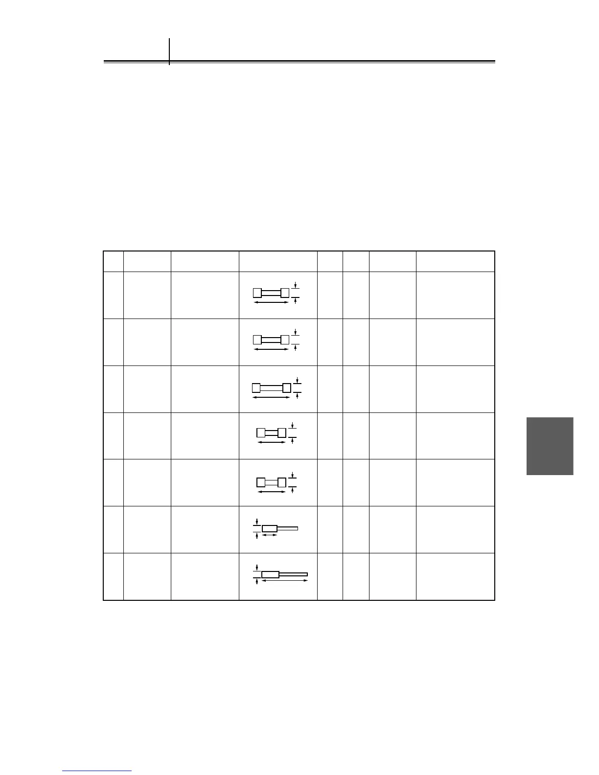
The parts listed in Table 7.4 are attached to the radar as the standard spare parts.
Table 7.4 Spare Parts 6ZXRD00193
7.3 Troubleshooting
Fuse
Fuse
Fuse
Fuse
Fuse
2
1
1
1
4
1
2
3
4
5
Carbon
Brush
Carbon
Brush
6
7
6
3
3
3
12
Inner display
unit
Inner display
unit
Inner display
unit
Display unit
monitor power
supply circuit
Display unit
NSK circuit
F1 to F4
F1
1
1
2
2
Inner scanner
unit (25 kW)
Inner scanner
unit (10 kW)
F5001 to
F5002
F5004
F5003
MF60NR-10A
(5ZFAD00018)
MF60NR-0.5A
(5ZFAD00013)
MF61-TS7
(5ZFAD00447)
TSC UL 1.5A
(5ZFCA00017)
MF51NN-0.5A
(5ZFAD00041)
54511-03
(BRXR05082)
S00152-5C-70
(BRXP00918)
ø 5.2
20
ø 5.2
20
ø 6.4
30
ø 6.4
30
ø 6.4
32
11
36
6
8
Parts Name Type/Code Shape (Unit : mm) In use Spare Parts No. LocationNo.
 Loading...