7 – 9
7.2
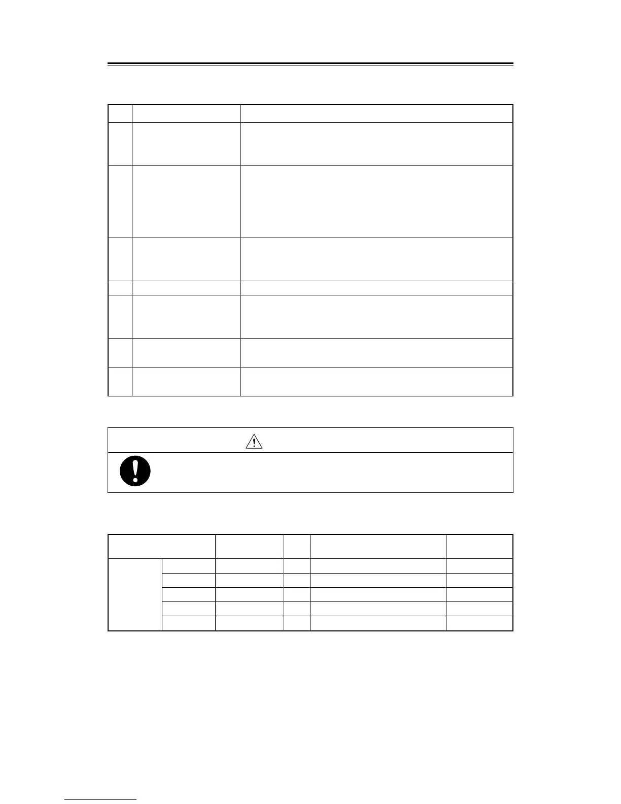
Table 7.2 (Continued)
No. Failure status Probable cause
8 a. Monitor failure or adjustment error.
b. The horizontal (HS) or vertical (VS) synchronous signal is fused.
c. CPU control circuit PCB (PC4401) failure.
9 a. The marker brilliance is adjusted to the lowest.
(See section “3.2 Preparation”).
b. CPU control circuit PCB (PC4401) failure.
10 a. Low ship's power.
b. CPU control circuit PCB (PC4401) failure.
c. Power (PC5101) failure.
11 a. CPU control circuit PCB (PC4401) failure.
12 a. CPU control circuit PCB (PC4401) failure.
b. Time base circuit PCB (PC4402) failure.
c. Low video brilliance.
13 a. "SYNC" or "STEP" is not properly set on the NSK (PC4201).
14 a. FAN failure. (B1)
Table 7.3 List of Fuses in Use
Location Parts No.
Rated
Protection circuit Type
current
Inner F5001 to F5002 10A MF60NR-10A
Inner F5003 7A Time lag MF61-TS7
Display unit Inner F5004 0.5A MF60NR-0.5A
NSK F1 to F4 0.5A PC4201 MF51NN-0.5A
Monitor F1 1.5A PG332 TSC UL 1.5A
In case of fan failure, radar unit will fail.
If fan failure occurs, stop operation at once, you should change the fan.
WARNING
Distorted display
No display appears even
after pressing the fixed or
variable range marker,
electronic cursor or panel
lighting key.
The screen returns to the
default during operation.
No alarm occurs.
Radar tracking does not
function.
The NUP or CUP display
cannot be selected.
"FAN" appears on the
lower of the screen.
 Loading...