Chapter 2. The Validator AVS Hardware
Kaye Validator AVS User’s Manual 24
3. Connect your inputs. Valid inputs are:
• Thermocouples T, J, B, S, R, N and K (see Connecting a Thermocouple later in
this chapter)
• Contacts (see Connecting a Contact later in this chapter)
• Voltage (see Connecting a Voltage Input later in this chapter)
• Current (see Connecting a Current Transmitter With a Precision Shunt Resistor
later in this chapter)
4. Release the two keys.
5. Repeat Steps 2 through 4 for remaining sensors.
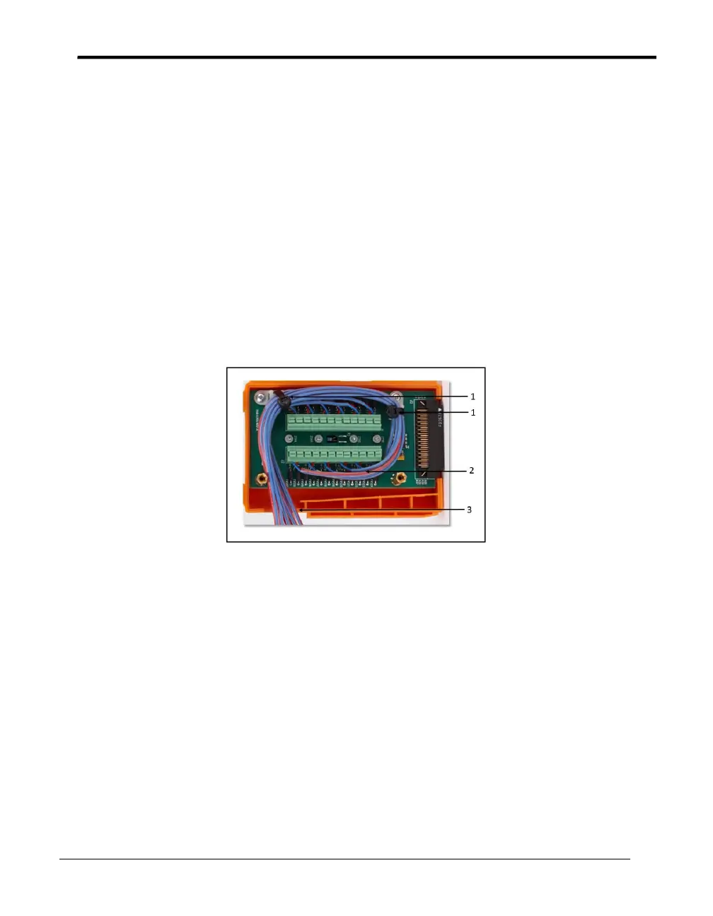
6. Once all sensors are connected, route the wire harness around the connectors and out
the drain hole. Secure the harness with the tie wraps provided. Follow Figure 9
below to maintain the thermal accuracy of the module.
Figure 9: SIM Wiring
Legend:
1 = Tie wraps (provided)
2 = Tie wraps (optional - user-supplied)
3 = Drain hole
7. Tighten the two screws in the top of the module to close the SIM.
8. Label the SIM with SIM slot number, SIM serial number, the Validator AVS serial
number, and the calibration date.
Note: To wire the dedicated 4-20 mA SIM, see document Z2036, “4 to 20 mA Sensor
Input Module.”