Chapter 2. The Validator AVS Hardware
Kaye Validator AVS User’s Manual 25
2.3.1a Connecting a Thermocouple
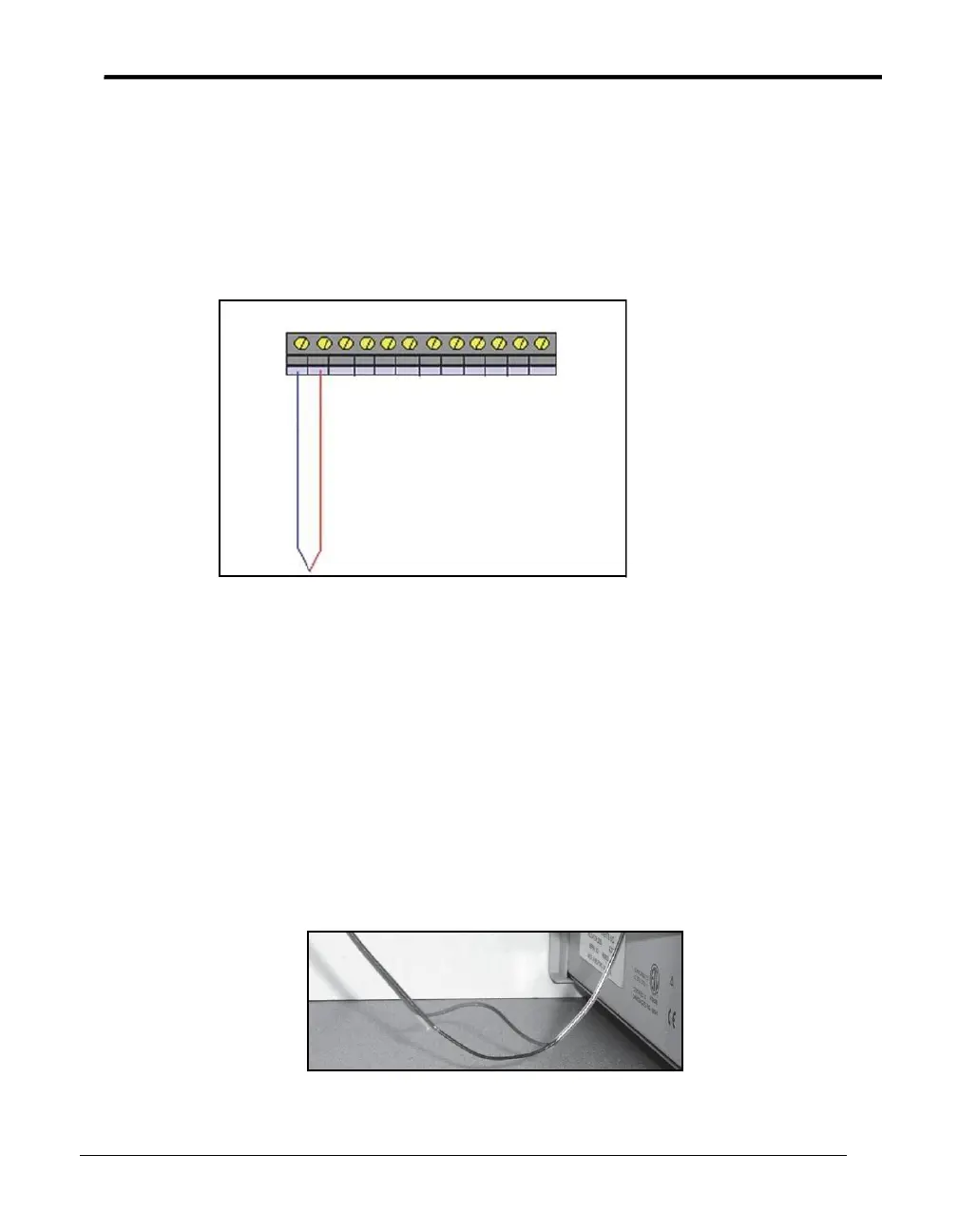
Connect types J, K and T thermocouples to the connectors as shown in Figure 10 below.
Cut through the outer insulation to separate the red and blue wires, and then strip back each
wire approximately ½ inch in order to make the connection with the connector.
+ – + – + – + – + – + –
1 2 3 4 5 6
Figure 10: Thermocouple Connections
Always connect the positive (+) lead to the positive (+) connector and the negative (-) lead
to the negative (-) connector. The negative thermocouple lead is normally red, in
conformance with ANSI standards.
Moist Heat Environments
When validating moist heat processes, a sealed PTFE tip thermocouple should be used
with a drip cut (shown in Figure 11 below) on the outer insulation close to the SIM module
to reduce the possibility of drawing moisture into the SIM. To add a drip cut, remove 4
inches (10 cm) of the outer insulation from each thermocouple at a point where natural
drainage can take place without water reaching the terminal screws (see Figure 11 below).
Figure 11: Drip Cut