Chapter 2. The Validator AVS Hardware
Kaye Validator AVS User’s Manual 29
2.3.1d Connecting a Current Transmitter
A dedicated 4-20 mA SIM is available that provides 12 current inputs and a connection for an
external power supply.
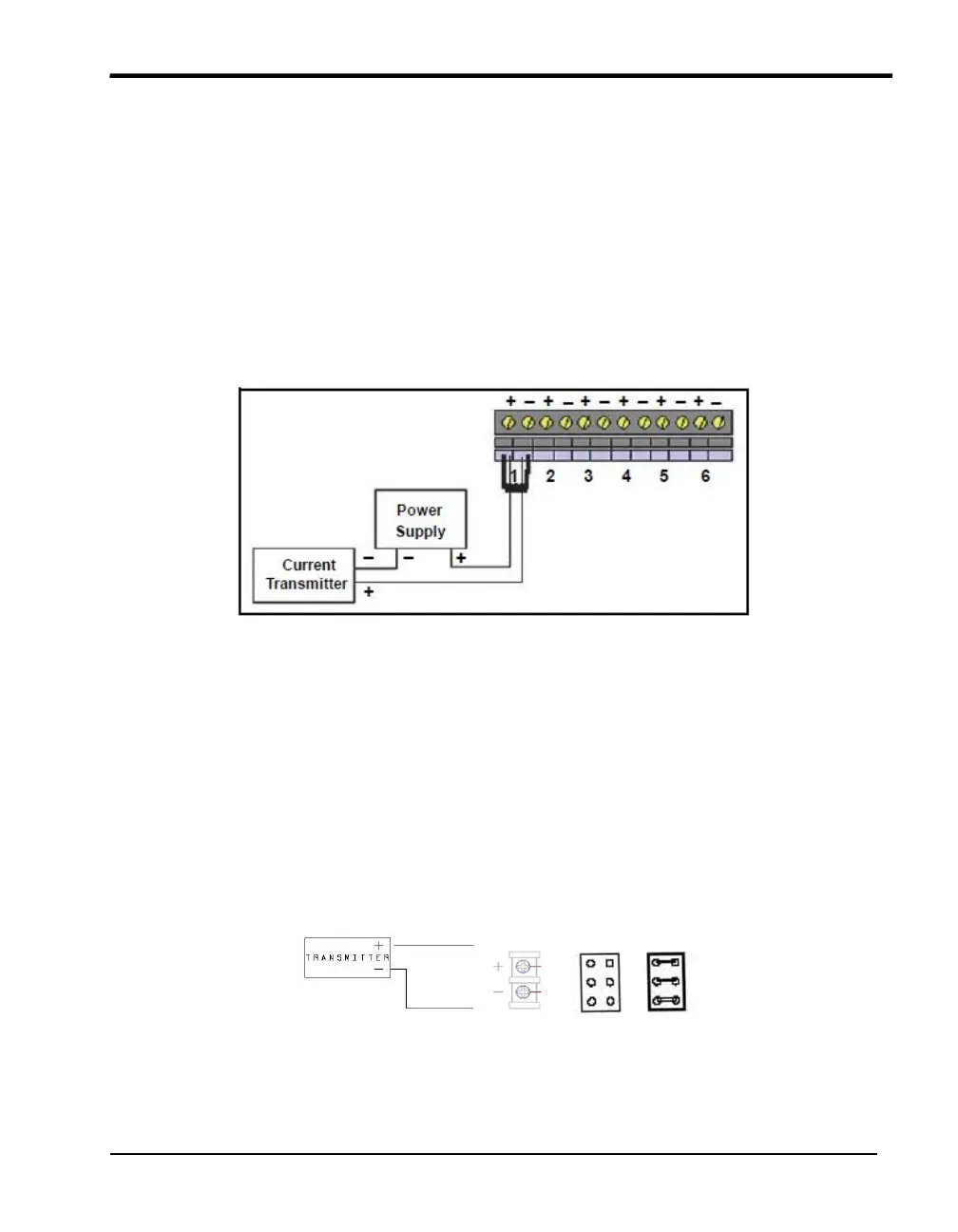
However, a current transmitter can also be connected to the standard TC-SIM. Connect a
precision shunt resistor to the connectors to convert the current to a measurable voltage, as
shown in Figure 15 below. A 250 resistor converts a 4-20 mA signal to a Voltage signal.
The 62.5 resistor converts a 4-20 mA signal to 0.25-1.25V. These voltages can be defined
in the TC setup as voltages accordingly. For easier handling we recommend using the
dedicated 4-10mA SIMs in the first place.
Figure 15: Current Transmitter Connection
The 4-20 mA SIM can be configured in two ways based on the power connections. The user
can switch between externally powered or locally powered, based on the placement of the
jumper blocks as shown in the figures. Please refer to the wording on the SIM itself to show
current jumper placement and orientation.
Sensors using 4-20 mA outputs can be attached in several different ways:
If the sensor requires less than 4mA to operate,
• Connect the positive lead to the positive input channel and the negative lead to the negative
input channel, as shown in Figure 1 below.
• Configure the jumper block for Local Power and attach 24V supply to J4.
Figure 16: Configuration for Sensor with
less than 4mA Power