49
4
Quadrant
Energy Analyzer
4
Quadrant
Energy Analyzer
SECTION 3 MENUS
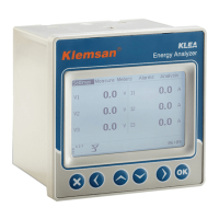
Settings->Setup->Analog output->Output1
Input mode V1 (L-N)
Output conn. 0-5V
Min. value 0.0
Max. value 0.0
Multiplier 1
V1 (L-N)
V2 (L-N)
V3 (L-N)
I1
I2
I3
P1
P2
P3
Q1
Q2
Q3
Fig. 3-39 Input mode
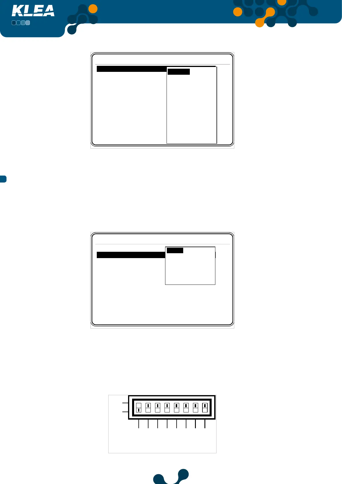
3.2.1.1.6.1.2 Output connection
Inside Output1 menu, press up and down keys to select (highlight) ‘Output connection’
menu item. When‘Output connection’ is selected, press OK key and the options in
Fig. 3-40 will appear on the screen. Press up and down keys to select the desired option
and press OK key to complete the setting.
Settings->Setup->Analog output->Output1
Input mode V1 (L-N)
Output conn. 0-5V
Min. value 0.0
Max. value 0.0
Multiplier 1
0 - 5V
0 - 10V
-5 - 5V
-10 - 10V
0 - 20mA
4 - 20mA
Fig. 3-40 Output connection
Assume that for analog output 1, output connection was selected as 0-5V
( Refer to Fig. 3.40). Then, operator should adjust the“analog output 1”dip switch as seen in
Fig. 3.41 (Vout1 -> ON ; Iout1 -> OFF). After the dip switch adjustment, setting will be completed.
ON
IOut4
IOut3
IOut2
IOut1
Fig. 3-41 Vout1 -> ON; Iout1 -> OFF