50
4
Quadrant
Energy Analyzer
4
Quadrant
Energy Analyzer
SECTION 3 MENUS
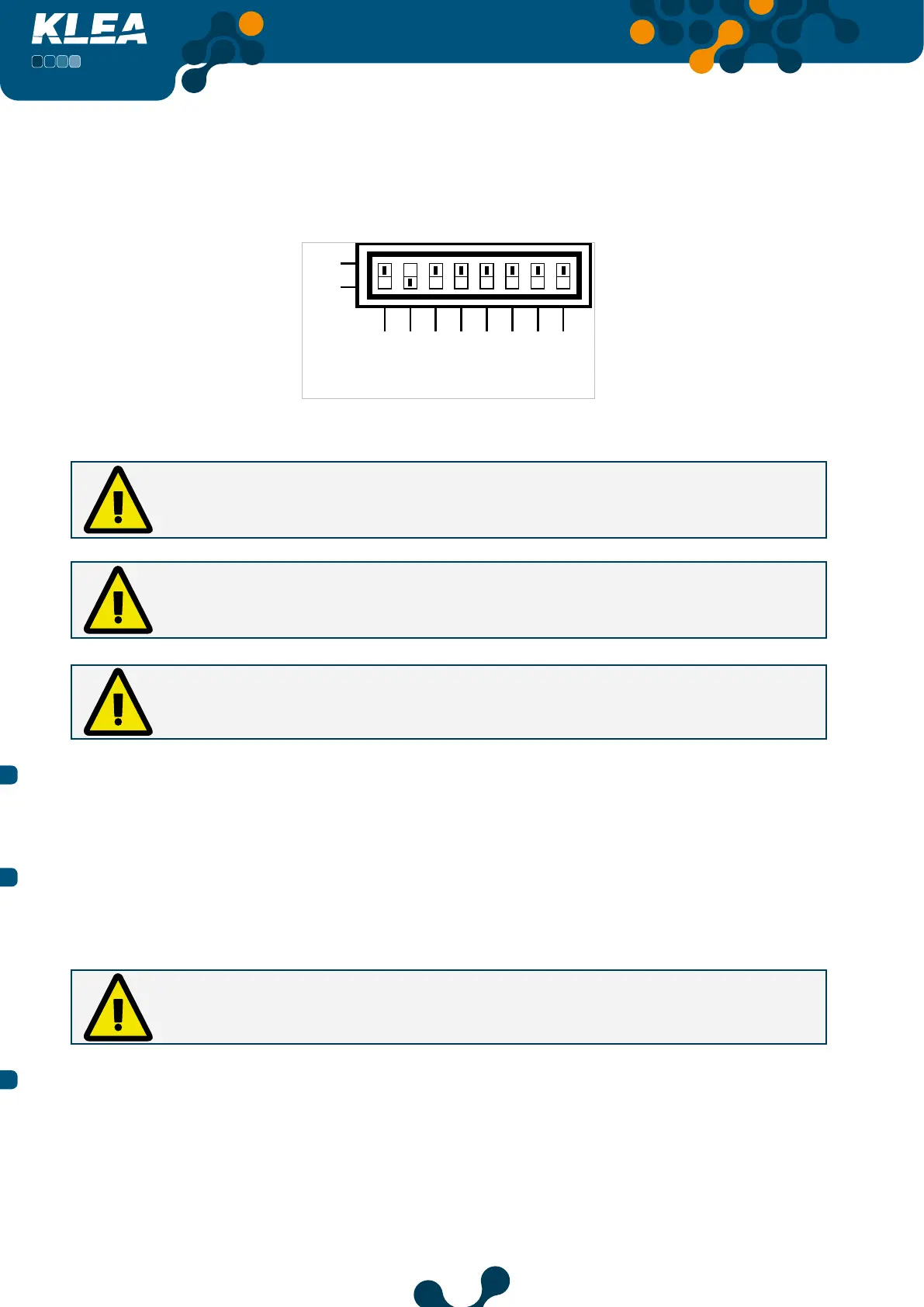
Assume that for analog output 1, output connection was selected as 4-20 mA (refer to Fig.
3.40). Then, operator should adjust the “analog output 1” dip switch as seen in Fig. 3.42
(Vout1 -> OFF; Iout1 -> ON). After the dip switch adjustment, setting will be completed.
ON
IOut4
IOut3
IOut2
IOut1
Fig. 3-42 Vout1 -> OFF; Iout1 -> ON
In order to obtain voltage output, Vout1 should be set to ON, and Iout1 should be
set to OFF. If both switches are ON or OFF at the same time, analog output will not
operate correctly.
In order to obtain current output, Vout1 should be set to OFF, and Iout1 should be set
to ON. If both switches are ON or OFF at the same time, analog output will not operate
correctly.
If the setting of output connection and setting of the dip switch are incompatible,
related analog output will not operate correctly.
3.2.1.1.6.1.3 Min. value
The minimum value for the selected input mode. Refer to 3.2.1.1.6.1.5 Multiplier setting.
3.2.1.1.6.1.4 Max. value
The maximum value for the selected input mode Refer to 3.2.1.1.6.1.5 Multiplier setting.
If “Min. value” and “Max. value” are adjusted to be the same, then analog output will
not operate.
3.2.1.1.6.1.5 Multiplier
When ‘Multiplier’ is selected, press OK key and the options in Fig. 3-43 will appear on the
screen. Press up and down keys to select the desired option and press OK key to complete
the setting. Multiplier coefficie t options are as follows:
• 1
• Kilo (1000)
• Mega (1000000)
 Loading...