2FD/2FF/2FG
1-5-22
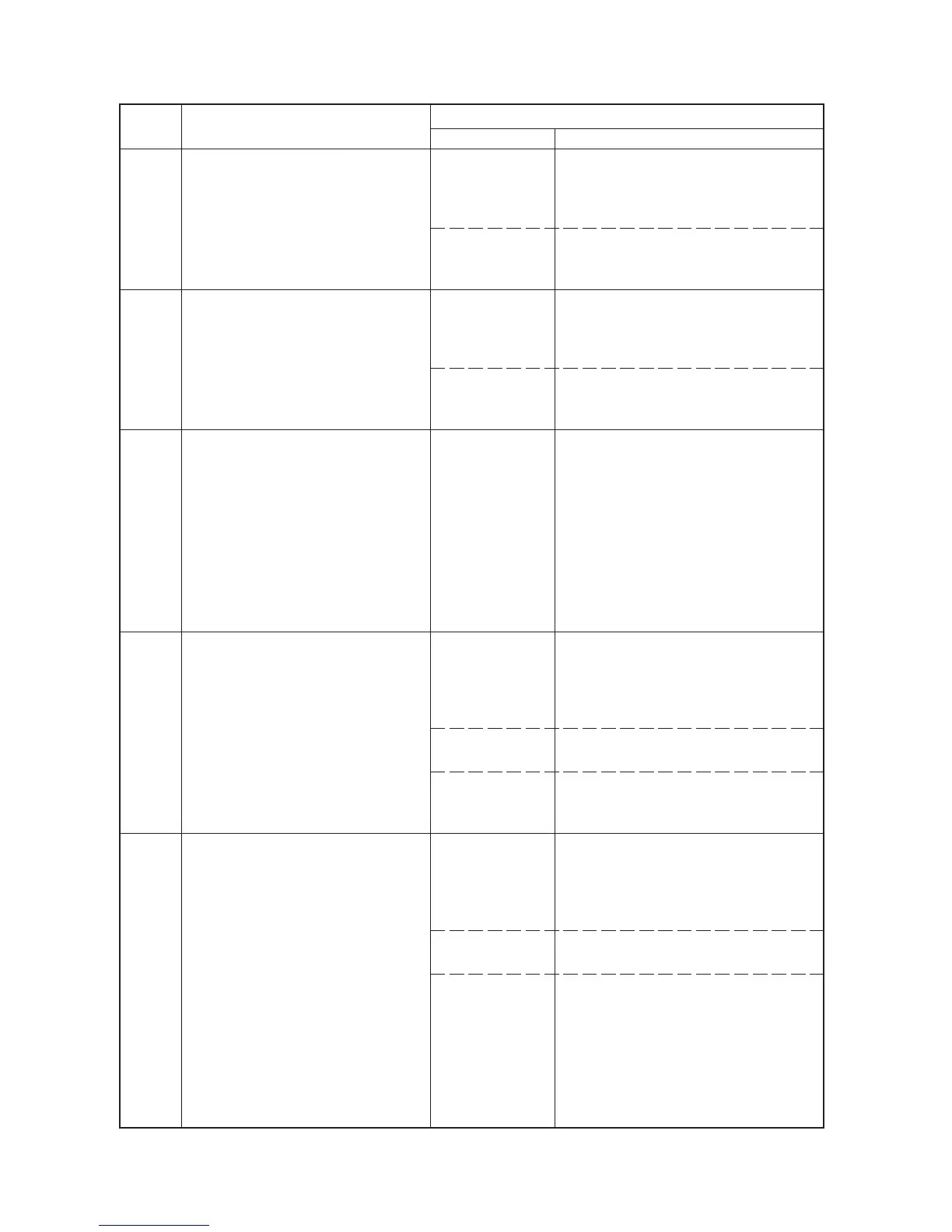
Code Contents
Remarks
Causes Check procedures/corrective measures
C0250
C0280
C0320
C0420
C0440
Scanner network board* communi-
cation problem
• There is no reply after 20 retries at
communication.
Fax control PCB* communication
problem
• There is no reply after 20 retries at
communication.
Energy save communication
problem
• Communication errors from the com-
munication microcomputer on the
main PCB.
No communication: there is no reply
after 5 retries.
Abnormal communication: a commu-
nication error (parity or checksum er-
ror) is detected five times in
succession.
Large paper deck*/paper feeder*
communication problem
• Communication errors from the com-
munication microcomputer on the
main PCB.
No communication: there is no reply
after 5 retries.
Abnormal communication: a commu-
nication error (parity or checksum er-
ror) is detected five times in
succession.
Finisher* communication problem
• Communication errors from the com-
munication microcomputer on the
main PCB.
No communication: there is no reply
after 5 retries.
Abnormal communication: a commu-
nication error (parity or checksum er-
ror) is detected five times in succes-
sion.
Poor contact in
the connector ter-
minals.
Defective main
PCB or scanner
network board.
Poor contact in
the connector ter-
minals.
Defective main
PCB or fax control
PCB.
Defective main
PCB.
Poor contact in
the connector ter-
minals.
Defective main
PCB.
Defective deck
main PCB/desk
main PCB.
Poor contact in
the connector ter-
minals.
Defective main
PCB.
Defective finisher
main PCB.
Check the connection of connector YC46
on the main PCB and the connector on the
memory PCB. Repair or replace if neces-
sary.
Replace the main PCB or scanner network
board and check for correct operation.
Check the connection of connector YC44
on the main PCB and the connector on the
memory PCB. Repair or replace if neces-
sary.
Replace the main PCB or fax control PCB
and check for correct operation.
Replace the main PCB and check for cor-
rect operation.
Check the connection of connectors CN3
on the main PCB and the connector on the
deck main PCB/desk main PCB, and the
continuity across the connector terminals.
Repair or replace if necessary.
Replace the main PCB and check for cor-
rect operation.
Replace the deck main PCB/desk main
PCB and check for correct operation.
Check the connection of connectors YC4,
YC5 on the main PCB and CN2 on the fin-
isher main PCB, and the continuity across
the connector terminals. Repair or replace
if necessary.
Replace the main PCB and check for cor-
rect operation.
Replace the finisher main PCB and check
for correct operation.
*: Optional

 Loading...


