2FD/2FF/2FG
1-3-45
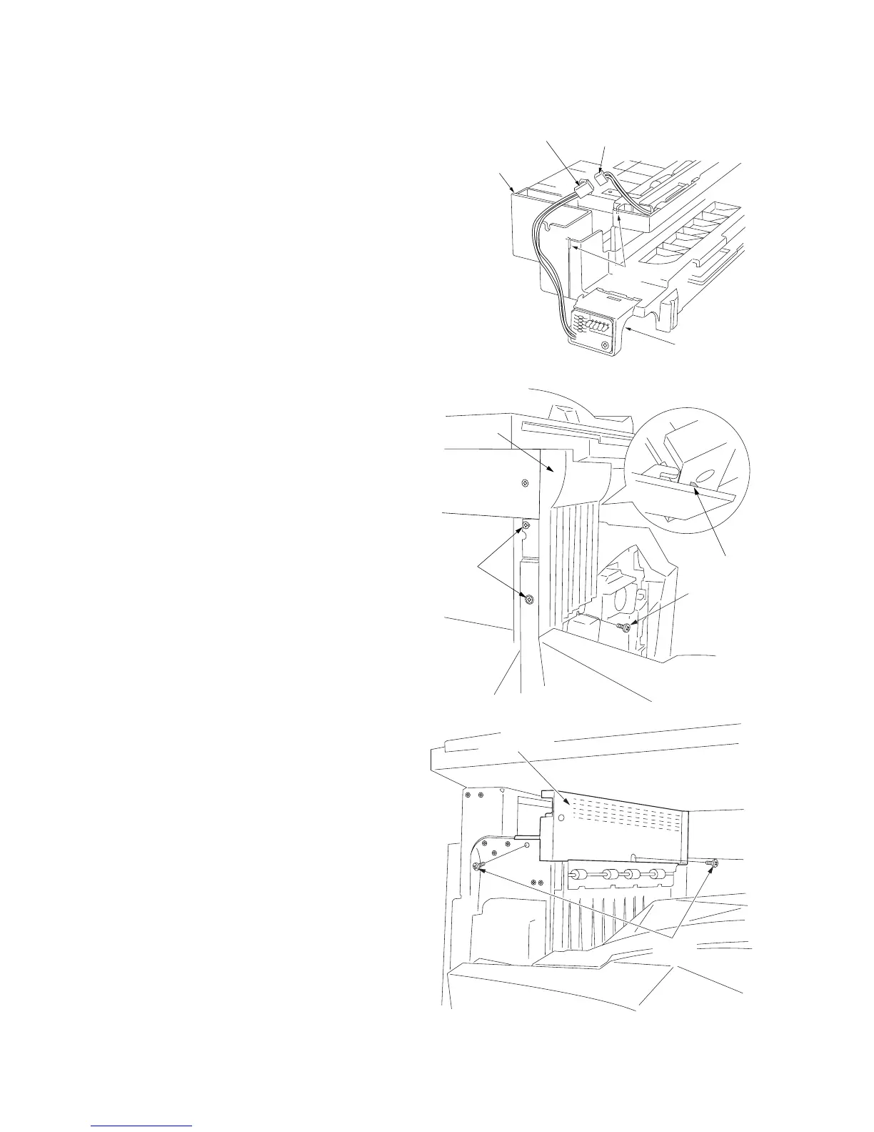
1-3-12 Installing the job separator (option)
Preparation
1. Insert the LED PCB into the job separator
and connect the 2-pin connector of the LED
PCB into the 2-pin connector of the job
separator.
* Arrange the wire into the two grooves of the
job separator.
Figure 1-3-103
Figure 1-3-104
5. Remove the two screws and remove the
ejection cover with the mounting plate.
Screws
Screw
Hook
Left front
cover
Ejection cover
Screws
2. Open the conveying cover and the front
cover.
3. Loosen the two left screws on the left side,
remove the screw on the front side, open the
hook on the right side, and remove the left
front cover.
4. Close the conveying cover and the front
cover.
Figure 1-3-102
Job separator
2-pin connector
2-pin connector
LED PCB
Grooves

 Loading...


