2FD/2FF/2FG
1-3-25
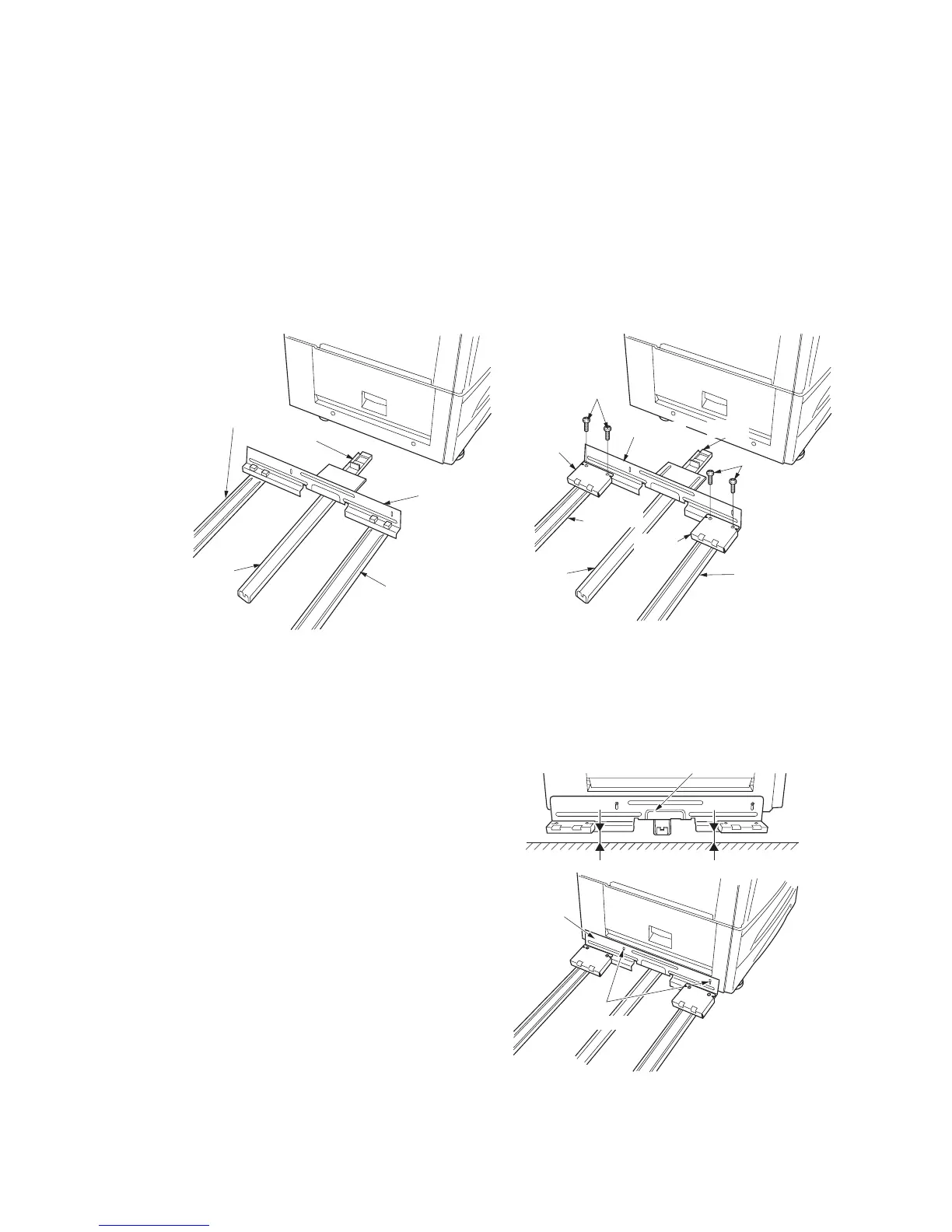
Figure 1-3-50
Figure 1-3-51
When the switchback unit is not to be installed
14. Orient the guide rail such that its pulley is
positioned toward the copier, and then fit a
caster rail to each side of the rail retainer.
When the switchback unit is to be installed
15. Attach a spacer to each end of the rail
retainer using two M4 × 6 binding screws for
each.
16. Orient the guide rail such that its pulley is
positioned toward the copier, and then fit the
caster rails to the spacer.
17. Secure the rail retainer to the copier using
two M4 × 10 binding screws such that the
front and rear gaps between the floor and rail
retainer are approximately 10 mm.
Guide rail
Caster rail
Caster rail
Rail retainer
Rail retainer
M4 × 6
binding screws
Rail retainer
Spacer
Spacer
Pulley
Caster railGuide rail
Caster rail
M4 × 6
binding screws
10 mm 10 mm
Rail retainer
Rail retainer
M4 × 10
binding screws

 Loading...


