2FD/2FF/2FG
1-3-27
Figure 1-3-57
Figure 1-3-55
Figure 1-3-56
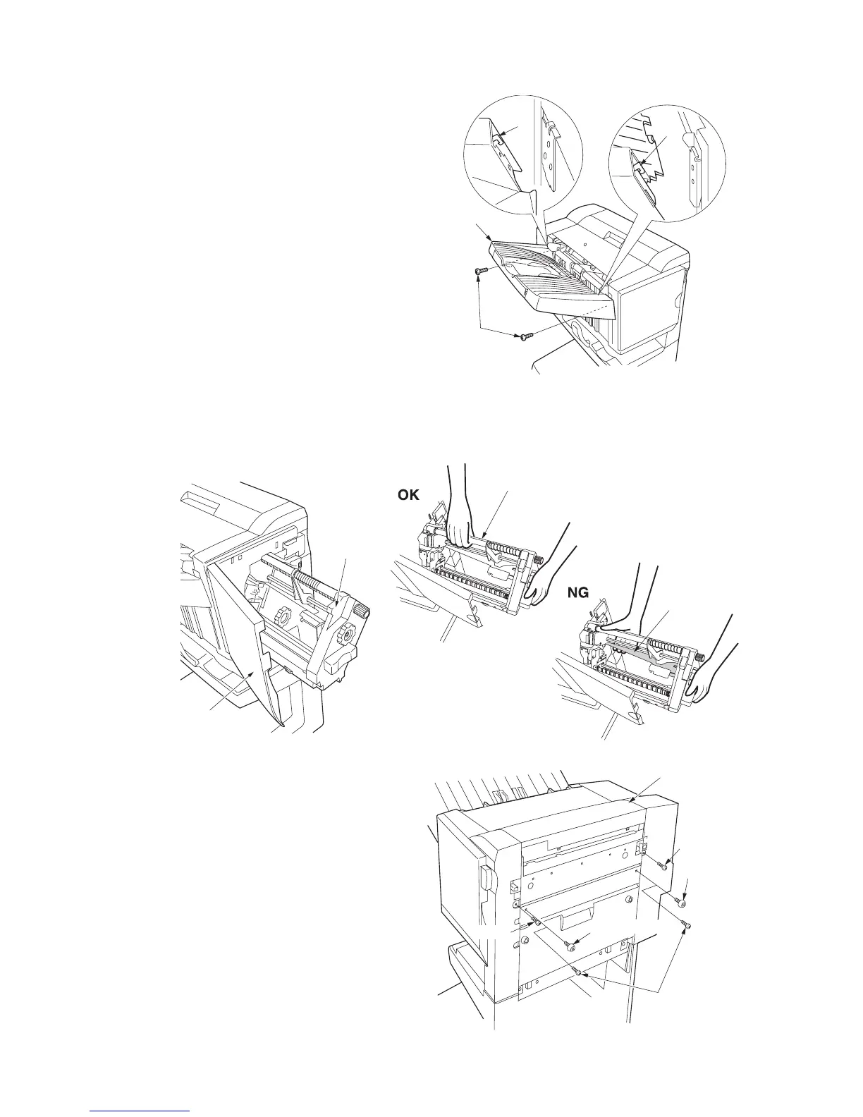
21. Fit the eject tray to the finisher by hooking the
two claws and secure it using two M4 × 6
binding screws.
22. Open the front panel and insert the stapler unit into the finisher.
When inserting the stapler unit into the finisher, be sure to grasp the upper portion (shaft) of the stapler unit as shown
in the illustration. If the plate in the middle portion (stay transport) is grasped, the unit may be deformed, resulting in
paper jams.
23. Close the front panel.
Installing the switchback unit
1. Remove the two support rubbers on the right
of the finisher and loosely fit the two M3 × 8
binding screws in their places.
2. Remove the two screws.
Eject tray
M4 × 6
binding screws
Claw
Claw
Stapler unit
Shaft
Stay transport
Front panel
Finisher
Support rubber
M3 × 8
binding screws
Screw
Screw
Support rubber

 Loading...


