2FD/2FF/2FG
2-1-13
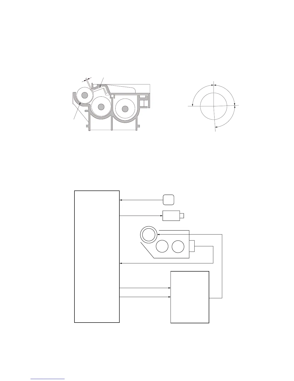
(1) Formation of magnetic brush
The developing roller consists of a magnet roller with four poles and a sleeve roller. Rotation of the sleeve roller around
the magnet roller entrains toner, which in turn forms a magnetic brush at pole N1 on the magnet roller. The height of the
magnetic brush is regulated by the doctor blade; the developing result is affected by the position of the poles on the
magnet roller and the position of the doctor blade.
A developing bias voltage generated by the high-voltage transformer PCB (HVTPCB) is applied to the developing roller
to provide image contrast.
A
A: Distance between the doctor blade and developing roller; 0.23 to 0.35 mm
N1:870 × 10
-4
T
N2:420 × 10
-4
T
S1:700 × 10
-4
T
S2:910 × 10
-4
T
N1
90
88
88
S1
S2
N2
Doctor blade
Developing roller
Figure 2-1-15 Forming a magnetic brush
TNFSOL
TNFSOL
TCS
TNS SIG
TNS
DB REM
24 V DC
HVTPCB
MPCB
CN1-1
DB
CN1-2
YC9-B2
TCS
YC9-A5
YC9-A9
YC7-1
YC7-2
Figure 2-1-16 Developing section block diagram

 Loading...


