2FD/2FF/2FG
1-6-18
3. Insert the two frame securing tools into the
positioning holes at the front and rear of the
scanner unit to pin the mirror 2 frame in
position.
Figure 1-6-34
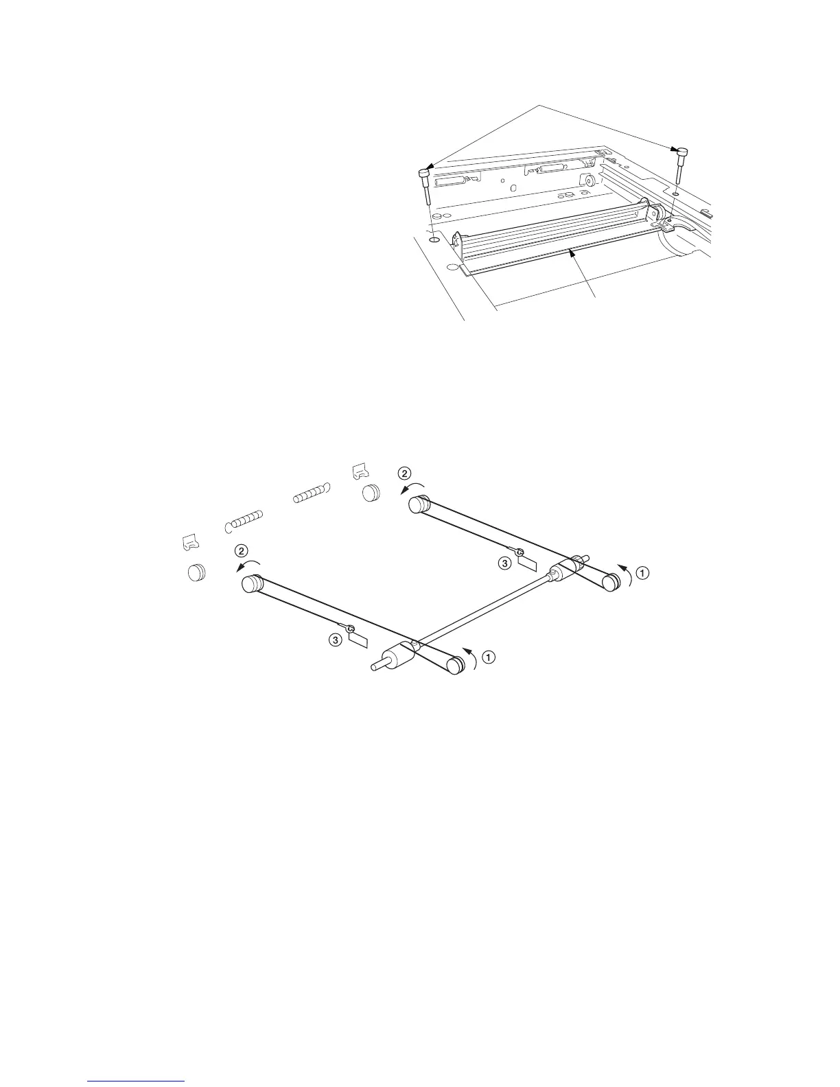
4. Loop the inner ends of the scanner wires around the grooves in the pulleys at the right of the scanner unit,
winding from below to above. ......................................................................................................................... 1
5. Loop the scanner wires around the inner grooves in the pulleys on the mirror 2 frame, winding from above to
below. .............................................................................................................................................................. 2
6. Hook the round terminals onto the catches inside the scanner unit. .............................................................. 3
Figure 1-6-35
Frame securing tools
Mirror 2 frame

 Loading...


