2KJ/2KH
2-2-1
2-2 Electrical Parts Layout
2-2-1 Electrical parts layout
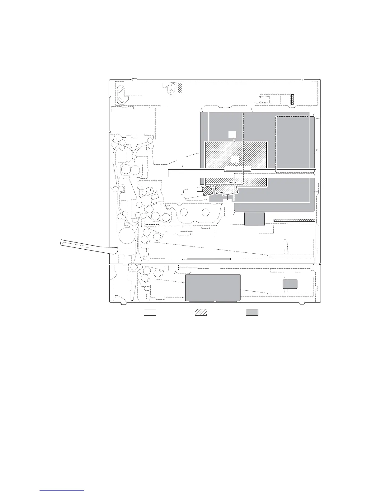
(1) PWBs
Figure 2-2-1 PWBs
1. Engine PWB (EPWB)................................... Controls the other PWBs, electrical components and optional devices.
2. Main PWB (MPWB) ..................................... Controls the operation panel and laser scanner unit.
3. Power source PWB (PSPWB) ..................... Generates +24 V DC; controls the fuser heaters.
4. High voltage PWB (HVTPWB) ..................... Main charging. Generates high voltages for transfer and high voltages for
separation.
5. Inverter PWB (INPWB) ................................ Controls the exposure lamp.
6. CCD PWB (CCDPWB)................................. Reads the image of originals.
7. Operation unit PWB (OPWB)....................... Consists of the operation keys and display LEDs.
8. LCD PWB (LCDPWB).................................. Controls LCD indication.
9. APC PWB (APCPWB) ................................. Generates and controls the laser beam.
10. PD PWB (PDPWB) ...................................... Controls horizontal synchronizing timing of laser beam.
11. Cassette PWB (CPWB) ............................... Relays wirings from electrical components.
12. Cassette main PWB (CMPWB)
*1
.................. Controls electrical components of the paper feeder.
13. Cassette heater PWB (CHPWB)
*1
................ Relays the cassette heater power.
14. Fax control PWB (FCPWB)
*2
........................ Modulates, demodulates, compresses, decompresses and smoothes out
image data, and converts resolution of image data.
Machine front
Machine inside
Machine rear
2
14
15
4
10
9
5
6
8
7
11
12
13
1
3
16

 Loading...