Repair GL16
7-16
5. Pull the return ribbons around their tracks
until all the lacing clips are accessible and
aligned at the front of the unit. Remove
all the connecting pins from the return rib-
bons. Position the return ribbons away
from the drive roll.
6. Place a tarp, plastic drop cloth, heavy
paper, or another temporary protective
covering over the delivery ribbons and re-
ceiving shelf.
7. Remove the screws and clamps at each
end of the drive roll (Figure 7-15) that hold
the friction material in place. Set the
clamps aside for later use.
8. Pull or cut off the old return ribbon drive
roll friction material.
9. Remove old cement from the drive roll
with a scraper, coarse sandpaper, or a steel
brush. Wipe away remaining residue with
a clean cloth.
10. Apply new cement evenly along the full
length of the drive roll and smooth with a
putty knife over the entire surface of the
drive roll (Figure 7-16).
11. Secure the friction material at one end of
the roll with masking tape so it does not
unwind during installation.
12. Carefully spiral-wind the friction material
around the length of the drive roll. This
procedure is easier with two people. One
person turns the drive roll by hand while a
second person holds the roll of material
and guides the material onto the drive roll,
pressing it firmly into place.
NOTE: The drive roll friction
material should be spiral-wound at
about a 45° angle. A more vertical
angle will use more cover material.
A more horizontal angle will use
less cover material.
13. Trim the ends of the friction material so it
is even with the end of the drive roll. Use
a nail to make a hole in the material where
the screws go through for the clamps. In-
stall the end clamps and screws.
14. Remove the temporary protective cover-
ing and clean up the area.
15. Refasten the return ribbons. Stagger the
positions of the lacing clips to give the flat-
work a smooth flow.
16. Remove the wooden wedges at the guide
assembly ends, or untie from above to put
tension back on the return ribbons.
17. Place the main drive chain on the sprock-
ets and, using a chain puller, bring the ends
close enough together to attach the clips.
If necessary, adjust the tension of the
chain. For more information within this
chapter, proceed to the Drive Chain sec-
tion.
18. Allow the cement to harden for 5 to 6
hours before operating the unit.
19. After the cement hardens, adjust the rib-
bons. For more information within this sec-
tion, go back to the
Return Ribbon
Tension Adjustment procedure.
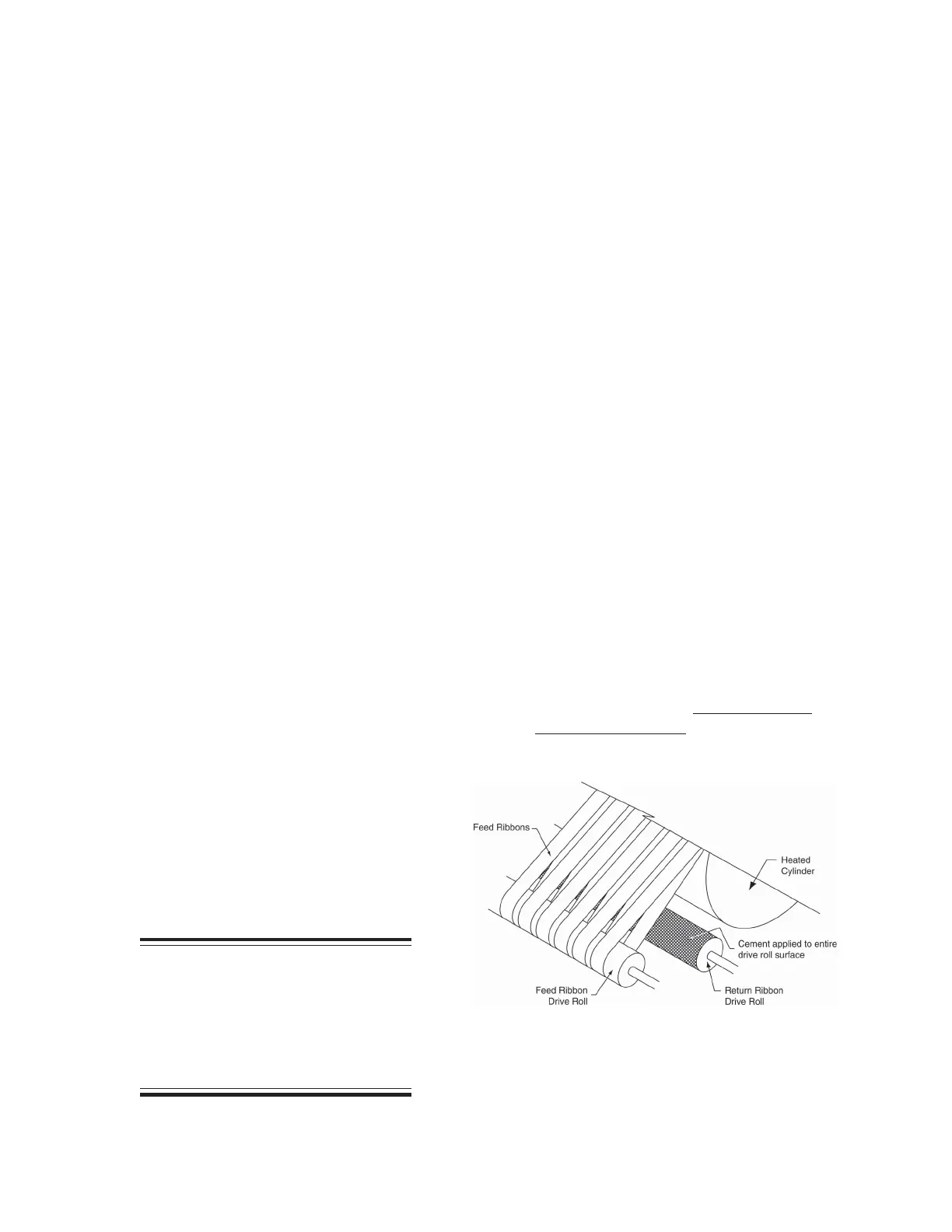
Figure 7-16: Cement secures the friction material
to the return ribbon drive roll.
 Loading...